Insight: When Simplicity Belies Complexity, the F.P. Journe Chronomètre Optimum
A very complex watch with no complications.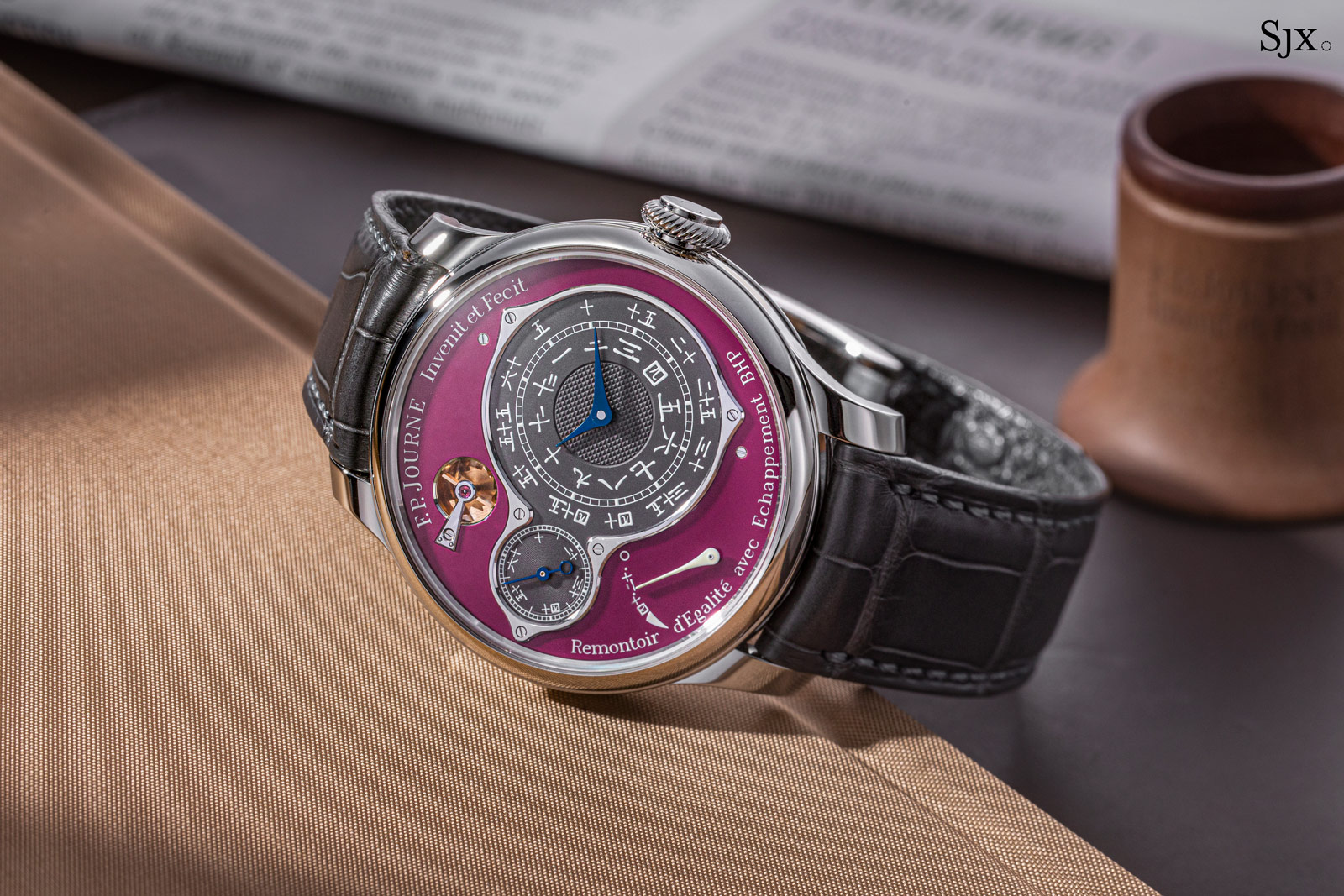
The Chronomètre Optimum is arguably François-Paul Journe’s most complex no-complication creation. Being a time-only watch, the Chronomètre Optimum displays the same amount of information as the entry-level Chronomètre Souveraine, albeit for more than twice the price, with the Chronomètre Optimum retailing for US$129,500 in platinum and a bit less in gold.
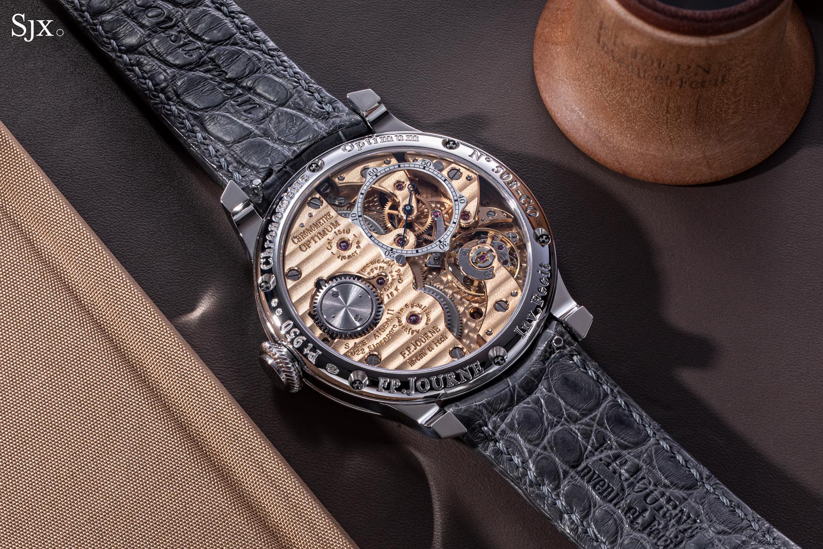
On a pleasantly asymmetric dial, the Chronomètre Optimum presents the wearer with the time, down to the second, and a power reserve indicator. Plain as the dial might seem, the Chronomètre Optimum’s appeal lies in its inner, and largely hidden, complexity. In fact, the cal. 1510 within ranks among the most sophisticated time-only movements on the market today.
Chronometry
Historically the tourbillon was never a complication, though it is often regarded as such today – though some prominent collectors disagree. In this context, it is difficult to label the features of the Chronomètre Optimum true complications. But since the timepiece was designed with chronometry in mind, its features of engineered accuracy might just qualify as a complication.
Chronometry in mechanical watchmaking is regarded as a marriage between accuracy and precision, as there is a nuance between the two. Accuracy is the quality of a watch or clock to have a timekeeping deviation as close to zero as possible, whereas precision relates more to the consistency and stability of the timepiece’s rate, rather than to a temporary lack of deviation. Hence, we might consider a watch that regularly gains 10 seconds a day to be precise, but we can hardly call it accurate. Chronometry is, in conclusion, the pursuit of steady and consistent accuracy in a timepiece.

The interior of the Kew Observatory in London that once tested watches and clocks, but has now been converted into a private home. Image – Kings Observatory
Since much of chronometry lies in consistency, it’s clear that any points of variance in a movement must interfere with its timekeeping. These variable factors can be divided in two classes: variance over short periods and variance over longer timeframes. For example, the tension in a mainspring decreases over its unwinding period. The barrel is rewound every 45 to 50 hours on average for manual-wind movements, which leads to a wide variance in torque delivery over relatively short periods.
In comparison, the slow degradation of oils and lubricants in the movement takes place over years. However, the change in their substance leads to great disturbances, especially in critical contact points like the escapement or in fast moving pivots.
These observations are hardly novel to watchmakers. The need for constant spring torque and the want for as little lubricant as possible have always been on the minds of precision clockmakers, who understood just how important consistency is. This led to the development of a number of ingenious constant force systems and high-performing escapements, coming from such illustrious makers as Le Roy, Breguet, and Berthoud. Some attempts even combined the two, giving birth to various constant-force escapements.
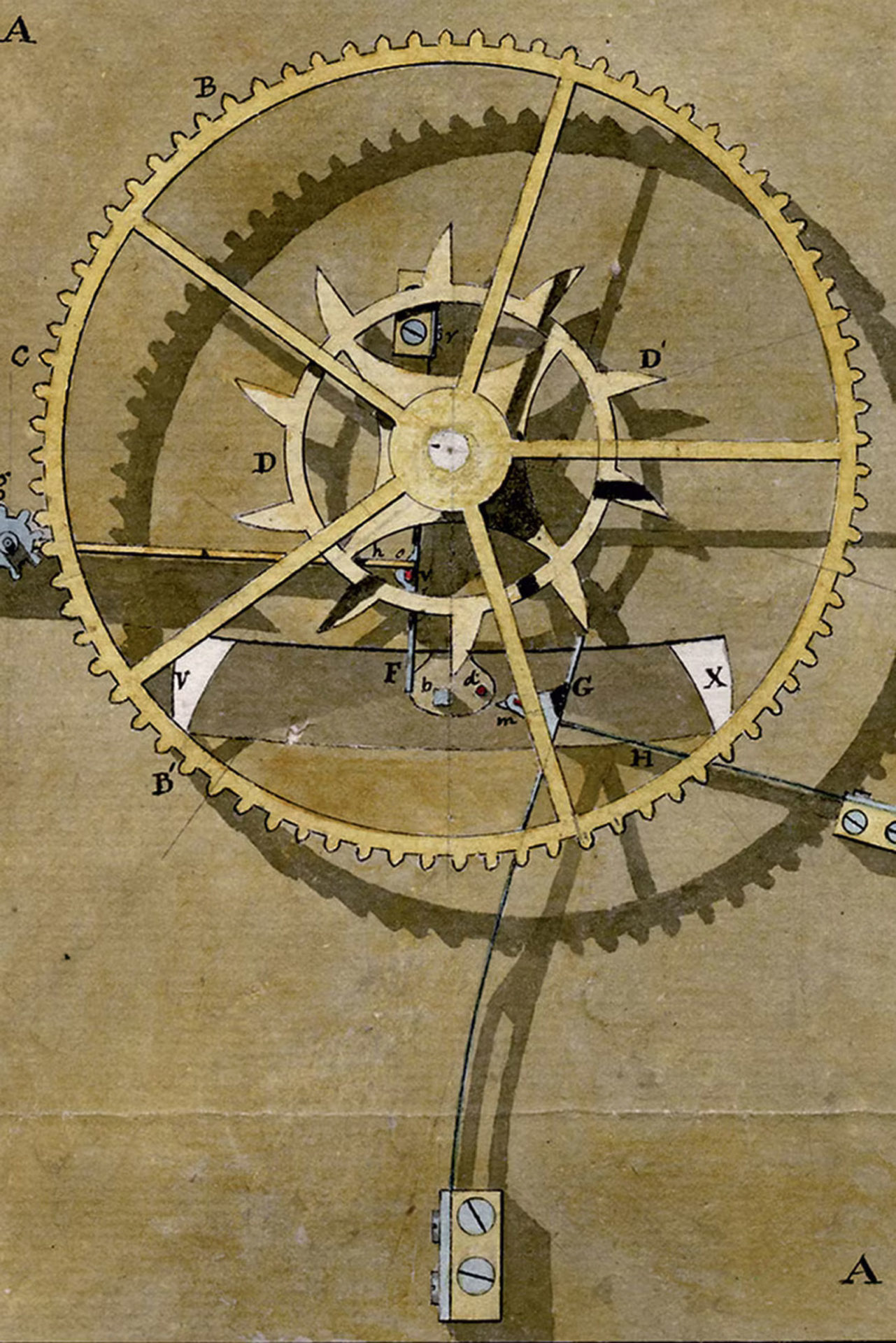
Breguet’s constant force escapement. Image – Breguet
The most important and celebrated chronometrical accomplishment of in the centuries prior to the 1900 was undoubtedly the Harrison H4 marine chronometer, which was completed in 1759 and set the standard for high precision timekeeping. The magnum opus of John Harrison, the H4 featured a great barrel and cone assembly (chain and fusee system), a constant-force device imposed on the gear train and a tweaked and improved sprung verge escapement. The end result was a timepiece that performed almost impeccably and with remarkable stability.
Perhaps unintentionally, the H4 piece outlined a general recipe for marine clock movements: a constant torque system that feeds the oscillator linearly with power and a well-engineered and efficient escapement.
Fast-forward a couple hundred of years and the Chronomètre Optimum seeks to follow, and perhaps improve upon, the very same recipe. Although not officially certified neither by COSC nor by any observatory, the architecture of the Chronomètre Optimum embraces certain design elements of traditional chronometers, such as the remontoire and double-wheel escapement.
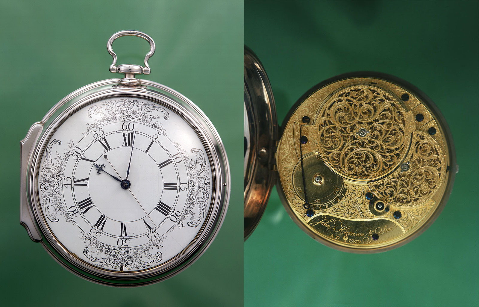
The H4. Image – National Maritime Museum, London
Optimal power delivery
Double barrels are a signature of F.P. Journe and found in most of his movements, going all the way back to his first tourbillon pocket watch. There are notable exceptions – the self-winding Octa, the Centigraphe, Résonance cal. 1520, and Tourbillon Souverain cal. 1519 amongst others – that employ only a single barrel but for reasons specific to the respective movement or complication.
Two (or more) barrels are traditionally set up either in series or parallel. Horological convention dictates a longer power reserve for series-coupled barrels and more stable timekeeping to the parallel connection, which is largely true.
In the case of two barrels connected in series, their respective angular velocities add up. Their compound number of developing turns is extended, which naturally makes for a longer power reserve. In the case of a parallel link between the barrels, the two mainsprings’ moments of force add up, making for a stronger and more balanced torque delivery.
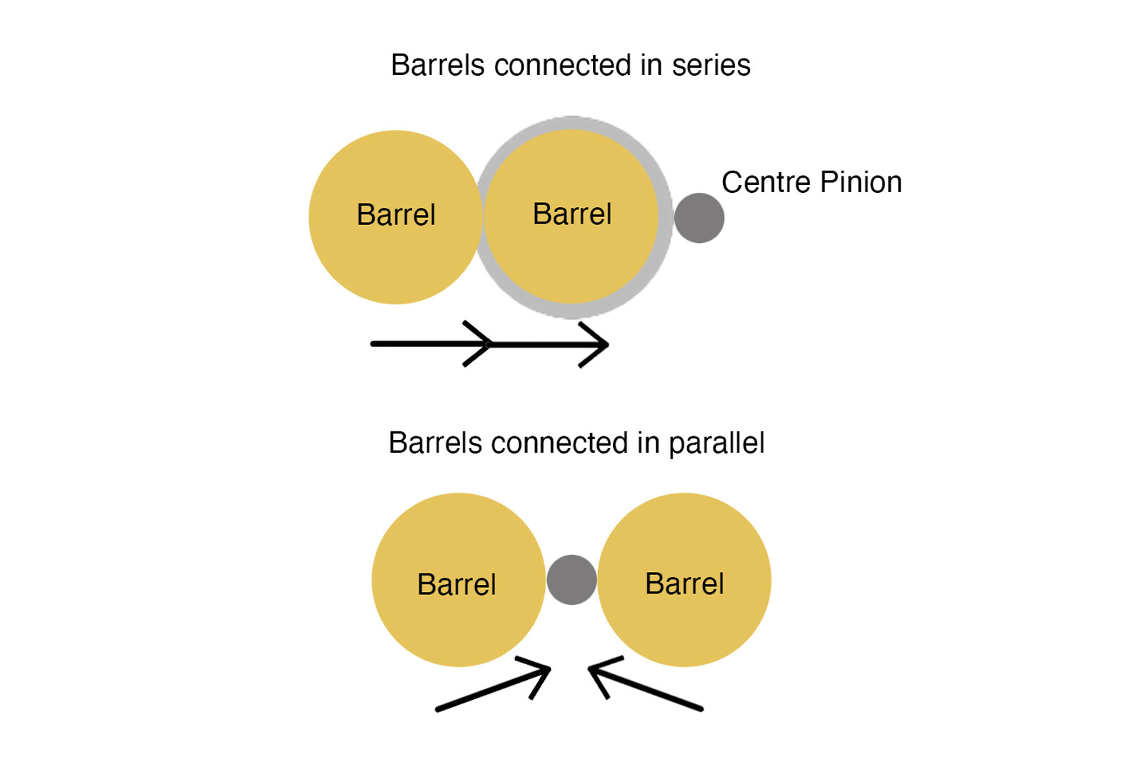
Another welcome effect of the parallel connection, empirically discovered by Breguet, is the virtual cancelling out of the side pressures in the centre pinion, due to equal strain coming from two opposing sides. The Chronomètre Optimum features two mainspring barrels coupled in parallel, which provide power for about 70 hours on a full wind.
Apart from this fairly conventional (but not definitive) cure to variable torque, Mr Journe opted for his clever remontoir d’egalité to ensure a truly linear power delivery to the regulating organ. The F.P. Journe remontoire is notable for standing apart from most comparable mechanisms.
Most other remontoires on the market are mostly based off what has become known as the Derek Pratt remontoire (although it was actually developed and patented by H. Barbezat-Bôle sometime in the 1920s). That concept revolves around a spiral spring (not entirely dissimilar to a hairspring, but stronger and stiffer) fastened to the escape wheel, which winds and discharges every second, its action governed by a detent-like wheel and a Reuleaux triangle-shaped cam.
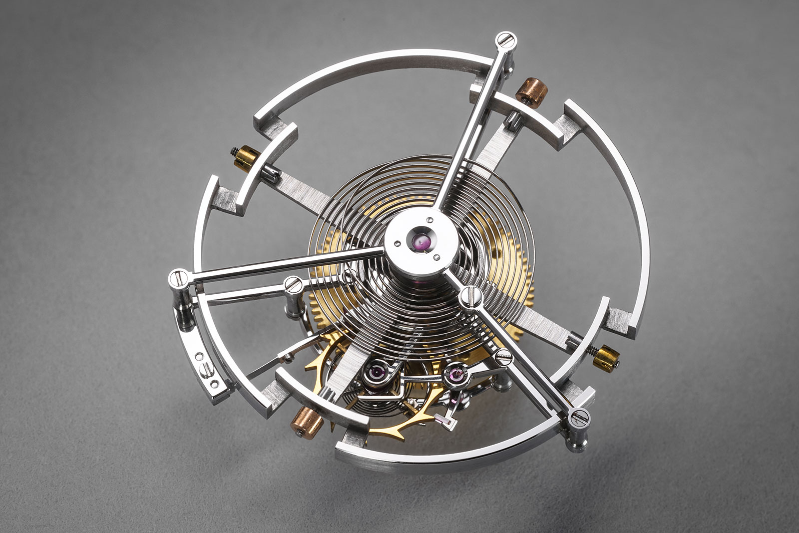
Derek Pratt’s remontoire within a tourbillon assembly
The F.P. Journe remontoire has a more distinct design as it is positioned further back on the going train and relies on a blade spring. As shown in the following figures, the action of the F.P. Journe remontoire is well thought out and ingenious, all while keeping the construction relatively simple.
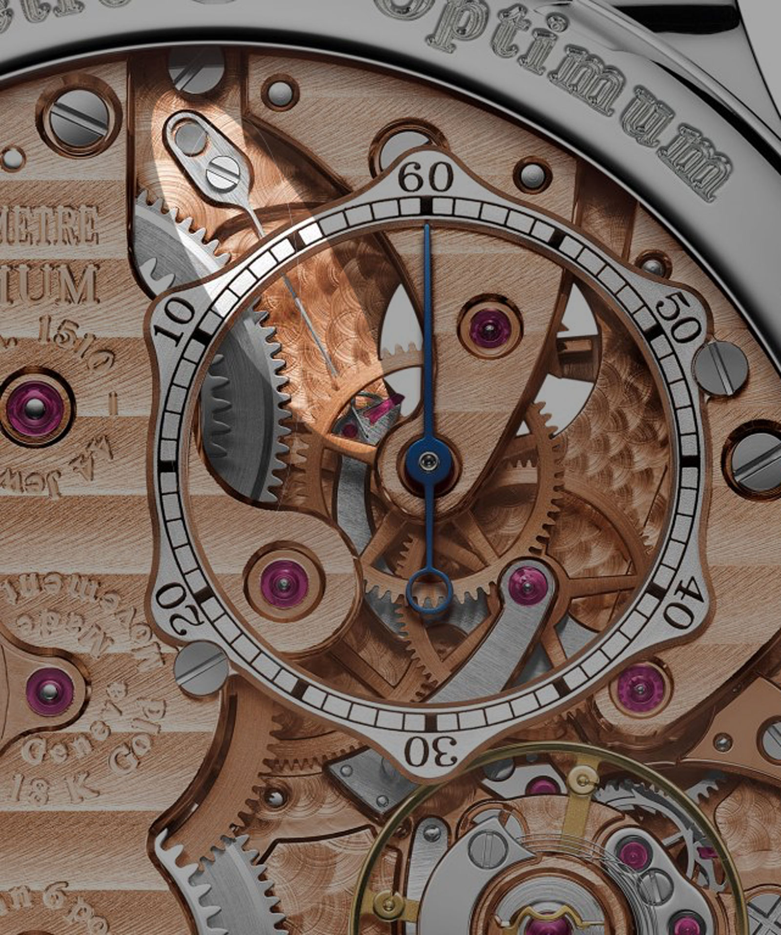
The F.P. Journe remontoir d’egalite with its blade spring
Figure 1 shows the remontoire in its unwound state. Gear 1 (orange) is the conventional third wheel of the going train. It joins with a fourth pinion 3, thus driving the fourth wheel 2 (green), which is conventionally the wheel that drives the seconds’ hand. This fourth wheel 2 connects to a detent-star wheel B (red). Pinion 3 extends equally under wheel 2, meshing with the great remontoire wheel 4 (yellow). Wheel 4 is not set in the mainplate, but rather on arm C. This organ C (grey) pivots freely around pinion 5, which belongs to the actual seconds’ wheel. It is this pinion 5 that is continuously powering the escapement.
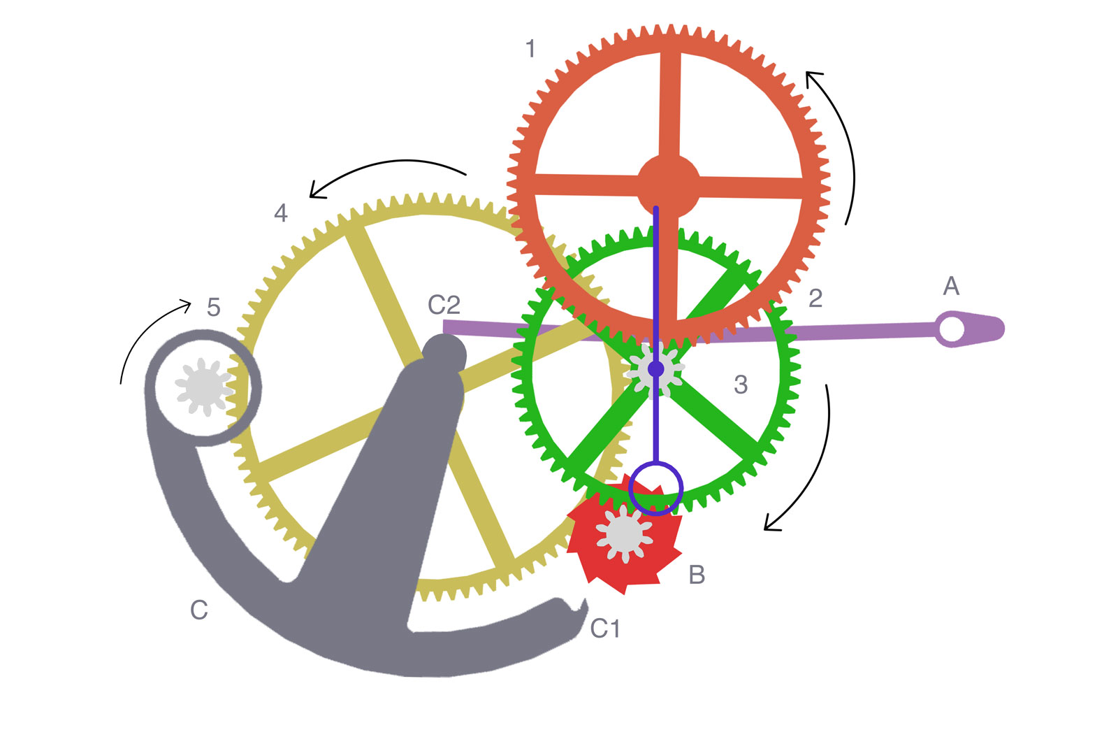
Fig. 1
Unlike conventional remontoire constructions, the great wheel 4 isolates 5 from the mainspring power flowing through 3 when the remontoire is in operation. The resulting arrangement is not unlike the intermediary coupling wheel in a chronograph’s horizontal clutch. Notch C2 of the remontoire arm C comes in contact with the remontoire spring A (purple). At the end of arm C, the latch C1 is meant to block the star wheel B, much like a locking stone locks a detent escape wheel.
In the run down sequence displayed in Fig. 1, the stiffness of a relaxed spring A keeps arm C in a neutral position. When the wound barrels start providing torque through the gear train, wheel 1 starts turning in the direction of the arrow, engaging the remontoire gearing. Pinion 3 starts turning, entertaining the great wheel in a counterclockwise motion, which further engages pinion 5. Kept in check by spring A, remontoire arm C remains stationary.
At some point, the escapement initiates the oscillation of the balance wheel. During the supplementary arc of the balance, the escape wheel is naturally locked in place, thus making of pinion 5 a temporary, fixed leverage point. Under the torque coming from the barrels and entertained by the fourth pinion 3, the great wheel 4 latches into the stationary pinion 5.
Using said pinion as a leveraging point, remontoire arm C gradually raises up counter clockwise against spring A and eventually cocks on star wheel B (the section encircled in light-blue). Star wheel B being subsequently locked, it brakes the entire gear train, all the way back to the barrels. From this moment on, the escapement is decoupled from the mainsprings’ power. This fully-charged position of the remontoire system can be observed in Fig. 2. The charging of the remontoire takes place swiftly, during one alternation of the balance wheel.
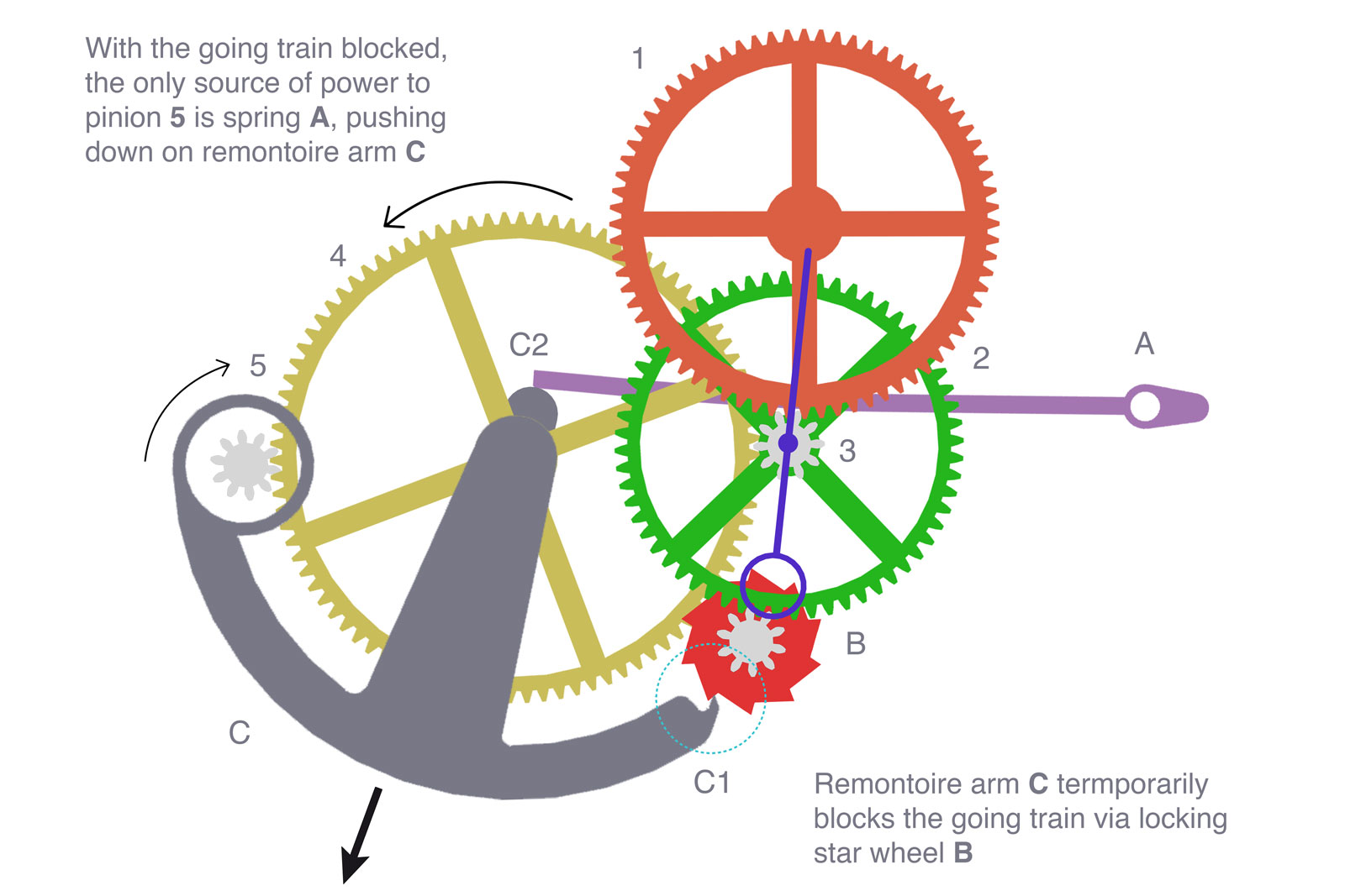
Fig. 2
The key point of this remontoire design is that it uses the tension stored in remontoire spring A to power the escapement, while pinion 3 is locked. When the escapement is unlocked, pinion 5 is free to rotate. It is thus driven by the stored energy from remontoire spring A, slightly pushing down on remontoire arm C, in a clockwise manner. During this motion, great wheel 4 turns counter-clockwise against the locked pinion 3, which in turn drives the free pinion 5 clockwise as to continue powering the escapement and impulsing the balance.
Then, the escape wheel is again locked, halting the remontoire. One can notice how the power delivered to the escapement comes directly from the spring A, completely independent from the mainspring barrels. During this sequence, arm C has moved fractionally, according to the arrow.
After a number of discharges (during an interval of 1 second), the eccentric movement of arm C causes the detaining latch C2 to unlock wheel B (Fig. 3). The gear train is thus released and a recharge of the remontoire is triggered. Leveraging on pinion 5, arm C rearms spring A and cocks into B; a cycle is complete and the remontoir is again set to supply power.
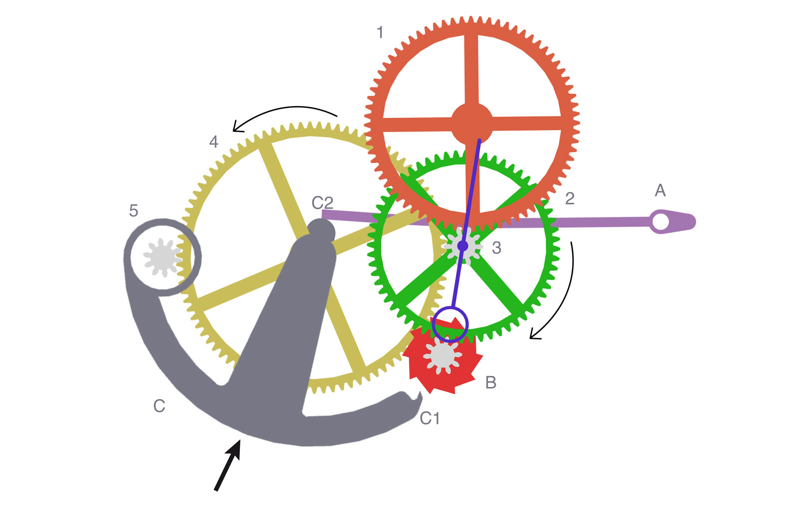
Fig. 3
The first F.P. Journe wristwatches featured this exact remontoire concept, which has undergone various tweaks since then and appears today in a number of his pieces. Back in 1999 when the first Tourbillon Souverain was launched, the remontoire was truly a novelty, hardly understood or valued by the larger public. However, the system was familiar to clockmakers and restorers. The remontoire employed by F.P. Journe shares some similarities with certain gravity remontoires found in table clocks, with the noteworthy mention that those were recharged by a system of weights, as opposed to a spring.
The F.P. Journe remontoire has its number of quirks. Firstly, it only engages for the first 50 hours of the power reserve. This value is not deliberately set by a dedicated decoupling mechanism, but is particular to the remontoire construction. Upon low power reserve, the torque coming from the barrels decreases sufficiently enough to meet spring A‘s tension. Thus, the remontoire arm C is suspended in a middle state, allowing the gear train to bypass the locking action of the star wheel B. This leaves the wheels free to spin and power the escapement directly.
Another thing to note is the motion of mobile 2. When the remontoire is engaged, it ticks once a second, which means that a seconds hand can be associated to it. This is the case with the newer F.P. Journe Tourbillons, which display dead-beat seconds on the dial.
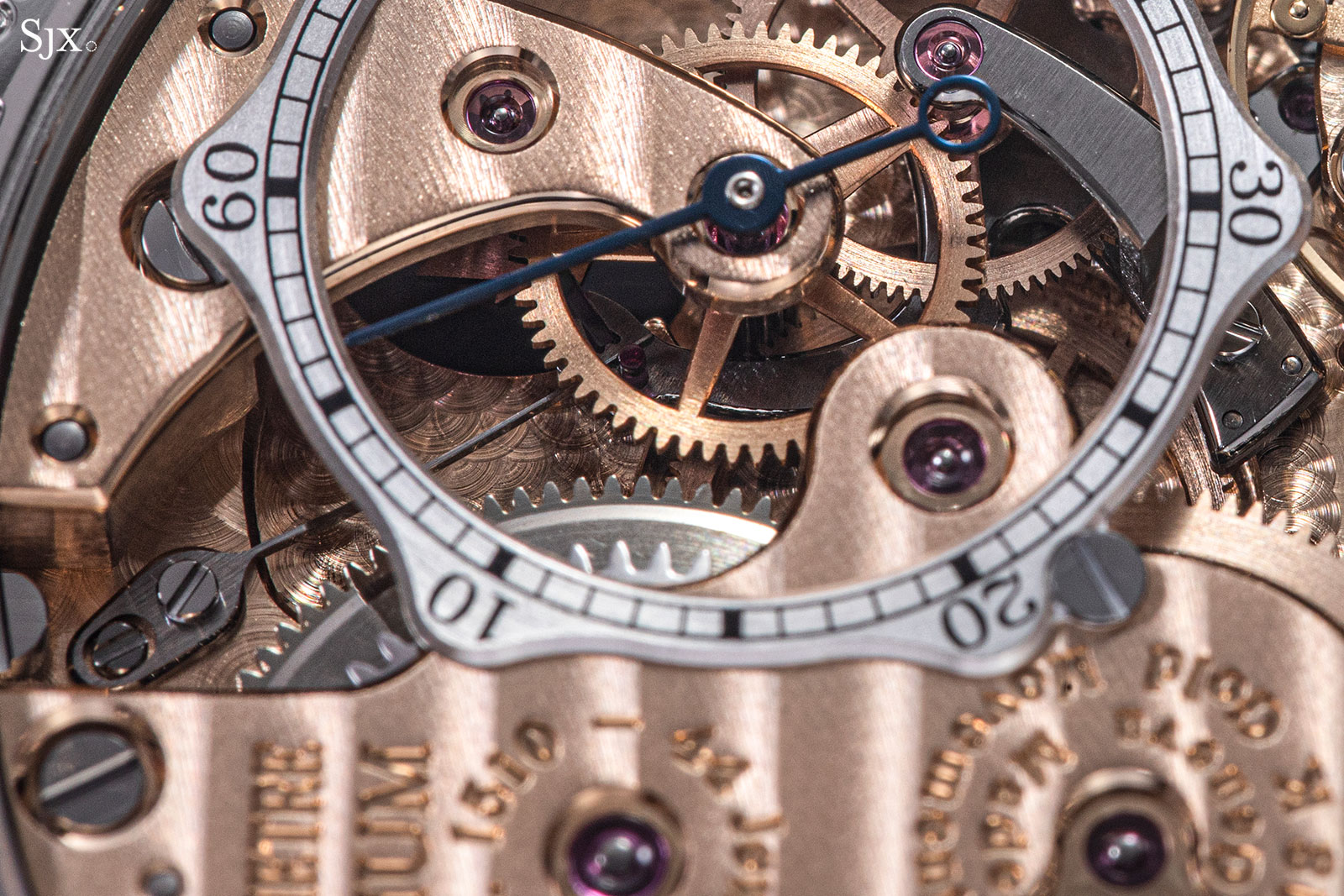
The blade spring visible below the seconds scale
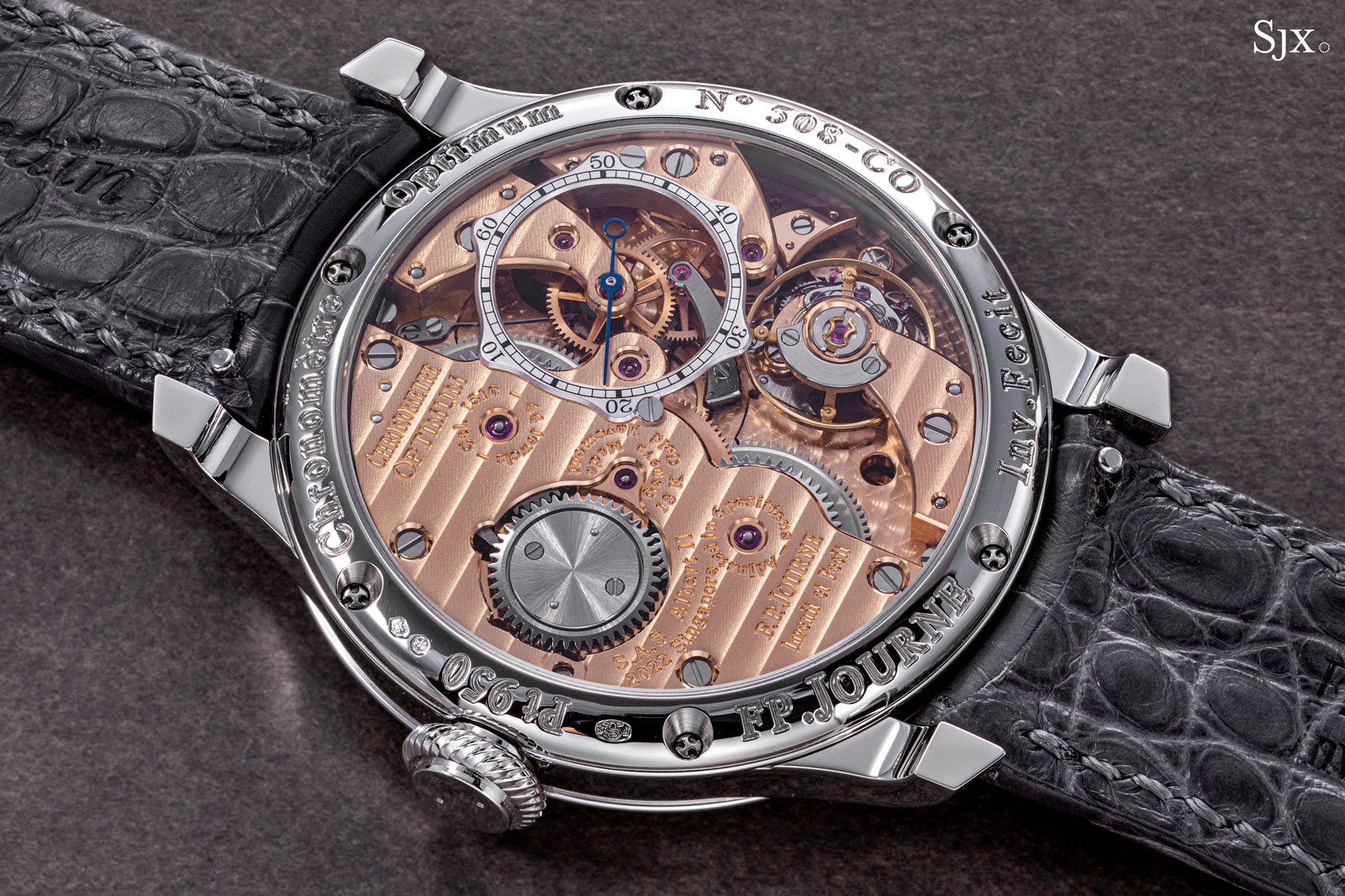
The Chronomètre Optimum exhibits a similar display through the case back. Intriguingly, the hand travels counterclockwise, due to the arrangement of the system.
Another interesting detail is the pair of arms over star wheel B, which pay subtle tribute to the wind flaps found in tower clocks remontoires. The purpose of those flaps was to air-brake the fly-wheel during recharging by acting like a reverse propeller. In the Journe remontoire the pallets are more of an aesthetic feature, due to the very small scale and relatively minimal rotation of star wheel B.
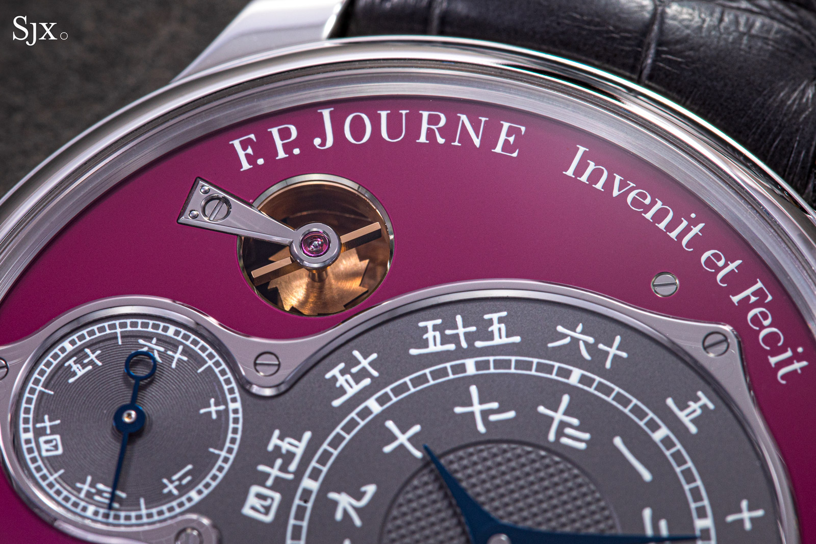
The arms and star wheel visible on the dial of the Chronometre Optimum
The EBHP
In every timepiece, the escapement is a device that maintains the oscillatory motion of a vibrating regulator, be it a pendulum or a sprung balance wheel. Due to internal molecular work and external resistive forces, any oscillating system is naturally dampened. In order to restore the energy lost during its vibrations, a pendulum receives regular impulses from a system known as an escapement.
Any escapement serves two purposes: impulsing the balance (or pendulum) and setting the gear train speed. In modern, detached escapements, the escape wheel sits at the end of the gear train, its pinion mating with the fourth wheel. It engages briefly with the balance, parting impulse, either directly or through an intermediate lever. As previously discussed, the escapement is commonly a cause of inconsistency in a timepiece, either due to poor design or degradation of its lubricants.
For Mr Journe, a scholar of Breguet’s work, the choice of escapement is almost self-explanatory. The natural escapement has rather caught the public’s eye in recent times, ever since it was adapted by the great Dr. George Daniels. In brief, a natural escapement comprises of two mirrored escape wheels, one driven by the other, which alternately impulse the balance wheel. Alternatively, it could be thought of as two mirrored detent escape wheels, joined by a pivoted detent and merged into a unitary system. This concept harnesses both the effectiveness of a tangential impulse, which requires little to no lubrication, and the convenience of a self starting capability, which stems from the mirrored design, as it will be explained later.
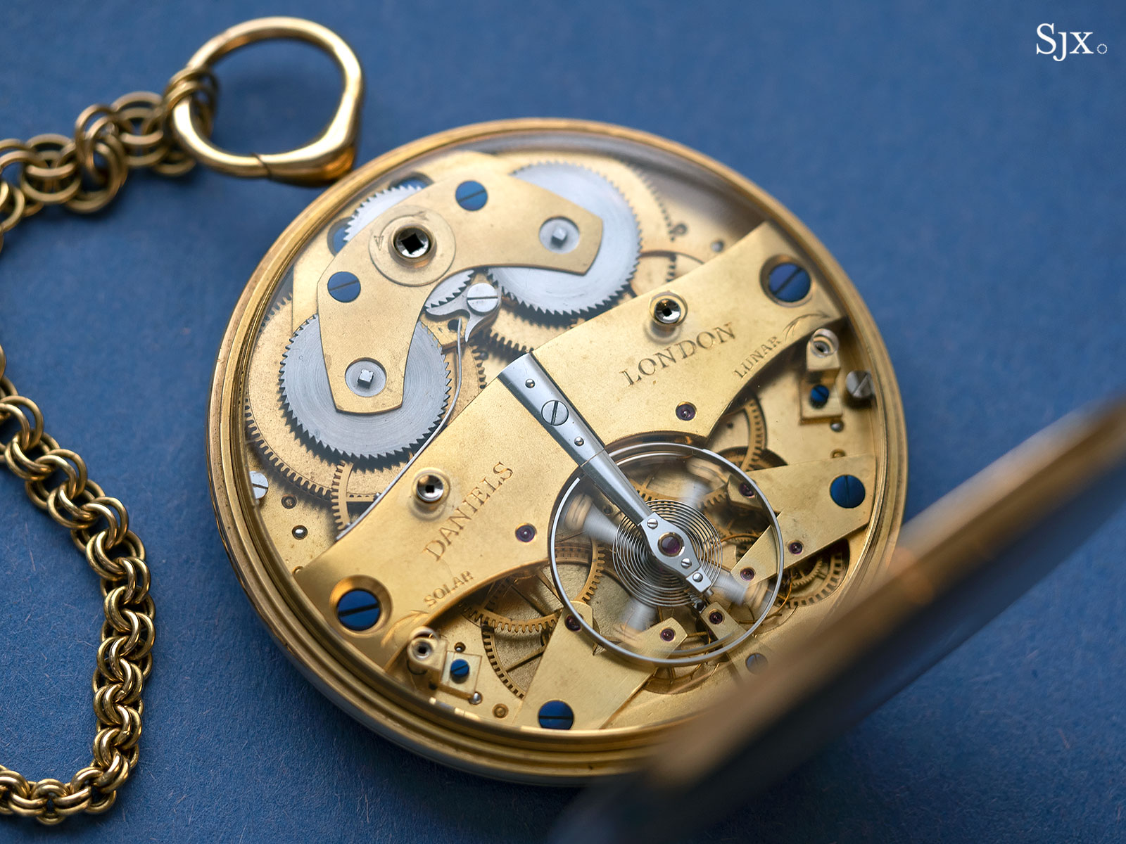
The Daniels Space Traveller’s Watch with its double-wheel escapement
As a side note, Daniels cleverly tweaked the design to have two separate gear trains powering each of the independent escape wheels. The Englishman never called his arrangement a “natural escapement”, for it generously differs from Breguet’s original invention. Curiously, Breguet coined the term because he considered a direct and double impulse to be the most natural form of impulse.
This makes it a bit difficult to precisely state whether the “natural” nomenclature actually requires the two escape wheels to be geared together or not. Other independent double-wheel escapements such as the Frodsham Double Independent are not thought to be natural escapements, as they have two complete and separate going trains powering the double escape wheels.
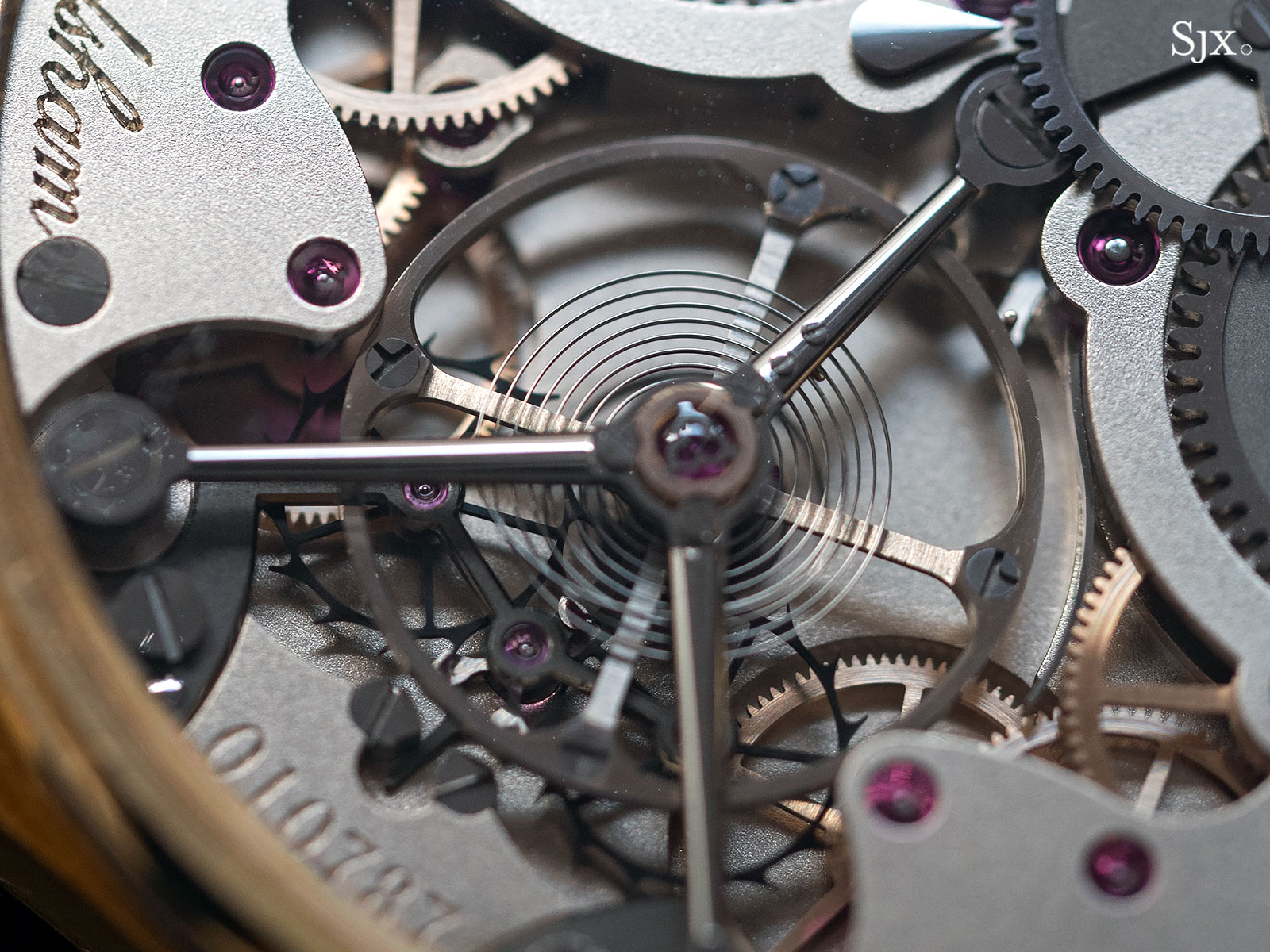
The Frodsham double-wheel escapement
F. P. Journe’s take on the natural escapement remains true to Breguet’s vision. There are no parts crafted from modern silicium, but rather an assortment of more traditional materials, such as beryllium-copper alloy, titanium and ruby. The creation was dubbed Echappement Bi-axial à Haute Performance (EBHP), which translates as “high-performance, double-wheel escapement”.
The EBHP is essentially a highly perfected natural escapement, conceived in keeping with the current watchmaking standards while keeping an eye on history. The invention ends up exhibiting both the advantages and disadvantages of Breguet’s original concept. However, there is one clever implementation that sets the EBHP apart from other similar escapements on the market: it borrows functionality from the commonplace Swiss lever escapement.
Improving upon the detent escapement, the natural escapement provides the balance wheel with double impulse, that is it imparts impulse to the balance each vibration, so twice an oscillation. By design, the detent only gives one impulse during each oscillation, which means it is generally unable to start on its own from run-down, although this is not always the case. There are instances when a detent escapement can self-start, depending on the escape wheel’s relative position to the balance. More often that not though, a detent-equipped timepiece requires a gentle shake to start the escapement.
Theoretically, this should not be the case with natural escapements: the relaxed hairspring keeps the balance in a neutral position, its pallets conveniently placed within the reach of either of the two escape wheels. Should the latter start spinning, it stands to reason that an impulse tooth is bound to come into contact with one of the pallets during its run. In practice however, due to the complex geometry involved, this may not always happen. The escape wheels may come in contact prematurely with the locking stones instead of the impulse pallets.
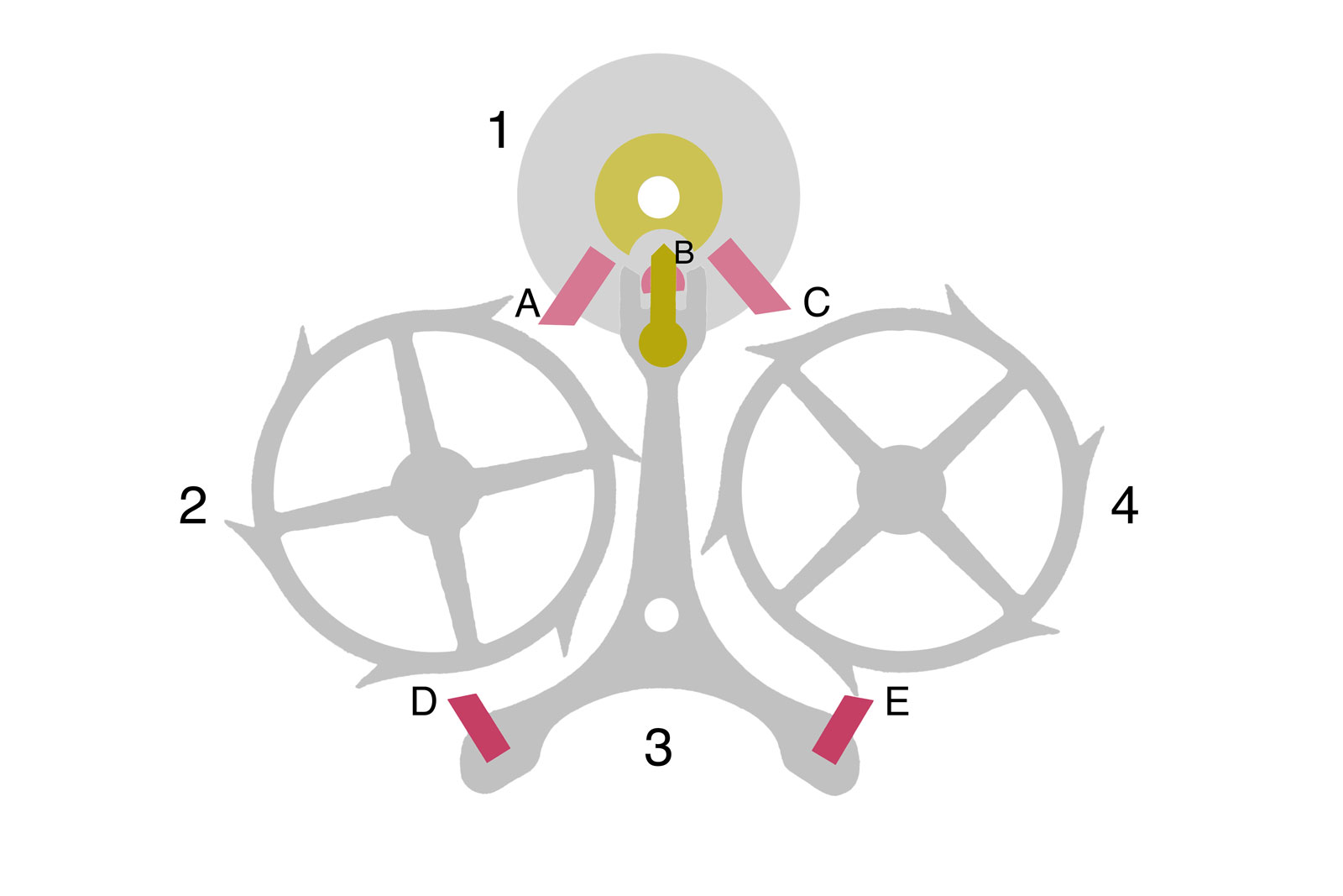
Fig. 4
To prevent this from happening, the two locking stones (D and E as seen in Fig. 4) on the EBHP each feature a sloped impulse face, just like Swiss lever pallets. The reasoning behind this curious choice is fairy simple. In the equilibrium sequence exhibited in Fig. 4, roller 1 engages lever 3 via pin B, keeping it in a neutral position relative to escape wheels 2 and 4. Figure 4 also shows one escape wheel tooth slightly touching the impulse flank of pallet E.
Should the watch be wound and the escape wheels put into motion, the tooth would slide along the sloped flank, effectively pushing the lever. The rocking of the lever engages the roller through pin B, disturbing the balance’s equilibrium. The oscillatory motion of the balance is thus initiated, even though the impulse pallets have not been directly engaged.
The described scenario is more of a failsafe, in case neither escape wheel manages to directly impart impulse to the pallets. The implementation is clever, but makes the overall system more difficult to set than other natural escapements. This elegant self-starting capability is often cited as a big advantage natural escapements have over the detent.
Having started the initial oscillation, the escapement cycles through the sequences of its operation as it follows. Figure 5 shows the EBHP during a locked position, with the balance going through its supplementary arc. Pallet E locks wheel 4 (which we’ll refer to as the driving wheel). Driven wheel 2 remains stationary as well, due to its link to 4. The two escape wheels are offset by 30°. The customary meshing gears underneath are not shown in the figures, but note that 4 is connected to the gear train by its pinion, while 2 is being carried along at the same speed by 1:1 ratio gearing. As long as the roller doesn’t engage lever 3 by its pin, the escapement is locked.
After accomplishing its clockwise arc, the direction is changed by the tensioned hairspring. The lever is secured by the safety dart and roller (yellow), which prevent it from accidentally unlocking due to external shocks. When the balance approaches its quiescent point, pin B engages the lever fork. A notch in the safety roller allows the lever to rock, driven by the balance. Stone E unlocks wheel 4. Both escape wheels start spinning, with wheel 2 impulsing the balance tangentially by striking pallet A, as displayed in Fig. 6.
The lever settles and locks wheel 2, while the balance disengages and begins its supplementary arc counterclockwise. At some point, the balance inertia is again overcome by the hairspring tension, which steers it back in a clockwise swing, as seen in Fig. 7. Pin B again engages the lever fork, unlocking wheel 2. The escape wheels start turning and wheel 4 provides pallet C with impulse very near to the balance’s quiescent point, as shown in Fig. 8. The lever is again set in a locking position, acting on wheel 4. The escapement returns to the sequence in Fig. 5. This cycle repeats during every full oscillation of the balance.
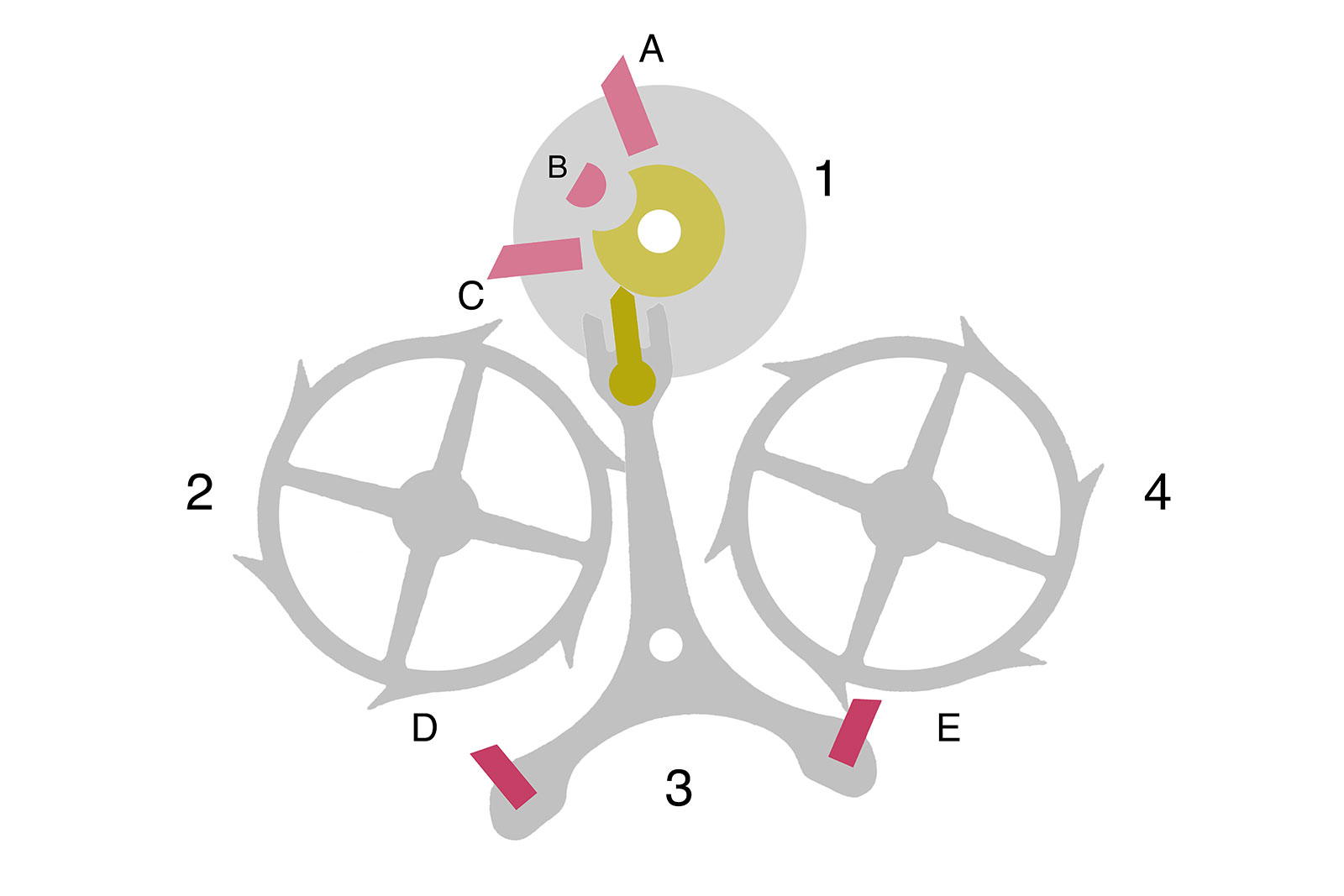
Fig. 5
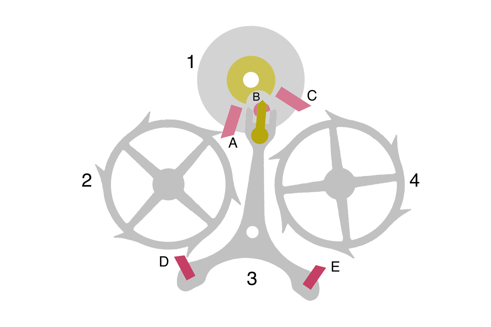
Fig. 6

Fig. 7
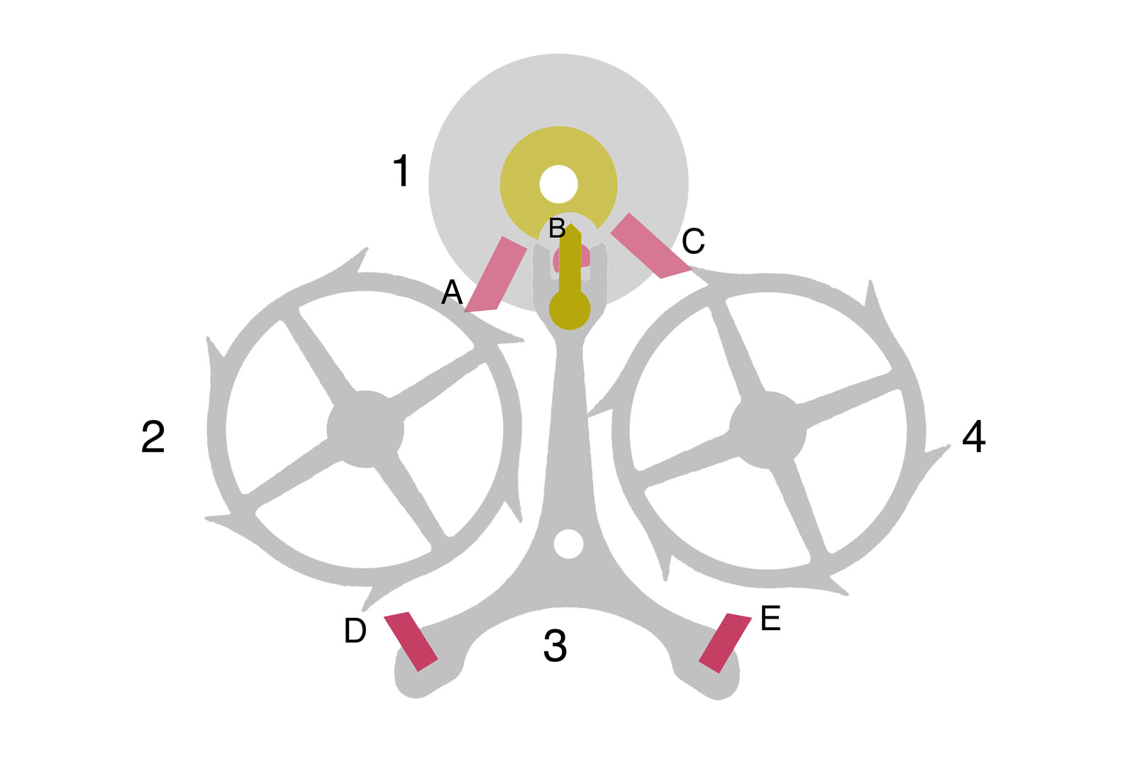
Fig. 8
The EBHP, although based on a old concept, is built and conceived in a very modern way, with the escape wheels and lever made from lightweight titanium. The safety dart-and-roller system is a relatively modern refinement, usually reserved for lever escapements.
Another feature the original Breguet design was lacking is the so-called draw. The draw (or draw angle) is a clever use of geometry that has become essential in ensuring safe lockings. By setting the locking stone at a certain angle in relation to the escape teeth, it binds lightly to the tooth flank. Since the locked escape wheel is kept tensioned by the mainspring and going train, it continuously pushes into the locking stone. Due to the aforementioned angle, the stone is always drawn towards the escape wheel’s centre, keeping the lever assuringly pressed against its banking pin.
In the eventuality of a strong shock that tends to destabilise the lever, its safety dart would touch the safety roller. Since that would generate friction and brake the balance wheel, any prolonged contact between dart and roller needs to be avoided. This is where the draw angle comes into play, effectively drawing the lever back against its banking and out of contact with the safety roller.
A side effect of the draw angle is a slight recoil (about 0.5°) of the escape wheel during unlocking, which is imperceptible and doesn’t really cause any harm. In conjunction, these safety devices ensure a stable and sturdy operation of the escapement, fit for wrist wear.
All these refinements make the EBHP a very sophisticated and finely-engineered escapement. But despite them all, the core design raises an important question: does it need lubrication? The direct impulse stages suggest a virtually dry operation, yet the presence of active draw and the sliding impulse implies a decisive need for lubrication. Each time the lever unlocks an escape wheel, the freshly unlocked tooth runs along the sloped flank, imparting a secondary, indirect and friction-generating impulse. Although the implementation makes for a quicker and more reliable start, it ends up working against the main selling point of the natural escapement, which is a completely dry operation.
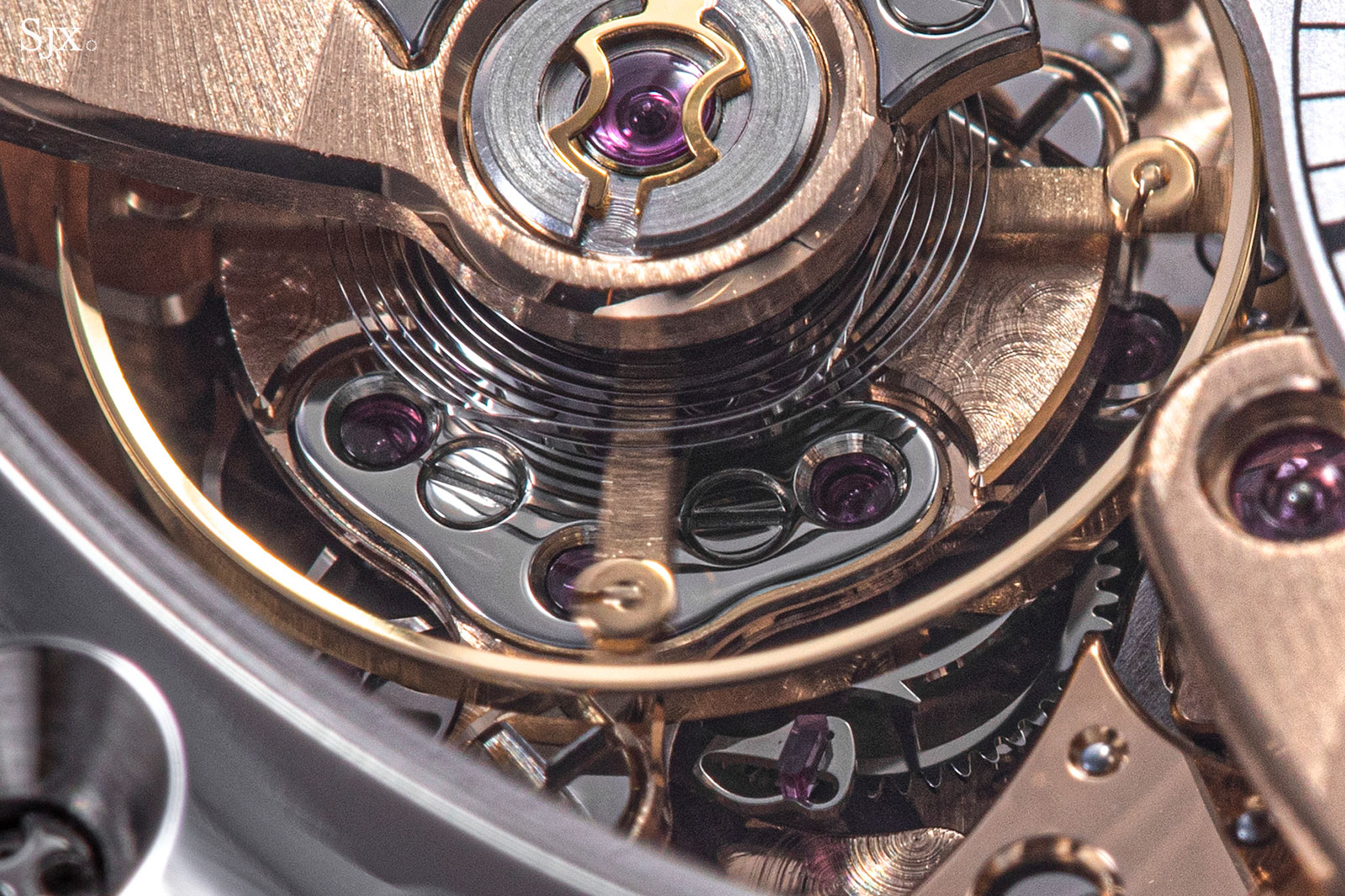
The twin escape wheels are barely visible under the balance
The EBHP also suffers from an issue inherent to all natural escapements: inconsistent impulse from the driven wheel. By design, the natural escapement is slightly asymmetrical, one escape wheel being driven by the gear train, while the other is carried along. As shown in the previous figures, the lever alternatively locks each escape wheel, individually. When the lever locks on wheel 2 (the driven wheel in this instance), the load from the mainspring travels all the way to wheel 2, keeping the entire gear train tightly tensioned. However, when the lever is locked on wheel 4, the load from the mainspring doesn’t extend to wheel 2 anymore, due to the backlash and play clearances between gears. Thus, the driven wheel sits idle and is prone to slightly flutter. This makes for uneven travel and impulse in wheel 4, which increases the escapement error and leads to unequal wear in the long term.
As it operates on a 3 Hz frequency, each escape wheel travels by one tooth, or 30°, during impulse. The two being linked, it adds up to 60° of total travel per oscillation. Thus, the angular velocity of the two escape wheels is 0.5 turns a second, or 30 turns a minute. In contrast, the traditional escape wheel in the higher frequency 5 Hz Zenith El Primero movement only makes 15 turns each minute.
In order to accelerate the escape wheels to such speeds, the Chronomètre Optimum’s gear train includes an additional gear and pinion, which come between the seconds’ wheel and the escape pinion. The task of accelerating the escapement is somewhat made easier by its titanium construction, which makes for an acceptably low inertia.
While conceptually the EBHP is superior to the Swiss lever escapement, its performance is somewhat dampened by the need for lubrication, the inconsistency of the driven escape wheel and the overall inertial losses caused by the large and complex construction. The patent on the EBHP suggests a lift angle of over 52°, which makes it greater than most Swiss levers. Comparatively, the Daniels double-wheel escapement only has a 36° lift angle. The addition of a supplementary mobile also lowers the global efficiency of the energy transmission between the remontoire and the escapement.
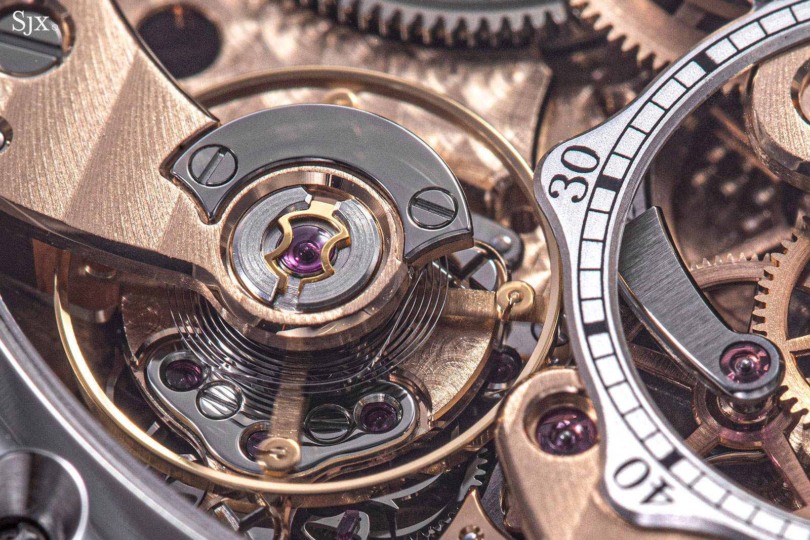
The balance wheel assembly itself is also worth mentioning. In typical F.P. Journe fashion, and as it’s become customary for modern watches, the balance is free-sprung, that is it has a set hairspring length. There are two ways to regulate a balance’s period and consequently fine tune a movement’s accuracy: either by modifying the hairspring’s active length or the balance’s inertia. Usually found in classical watches, a regulator stud limits the hairspring’s breathing between two pins and allows adjustment of its active length.
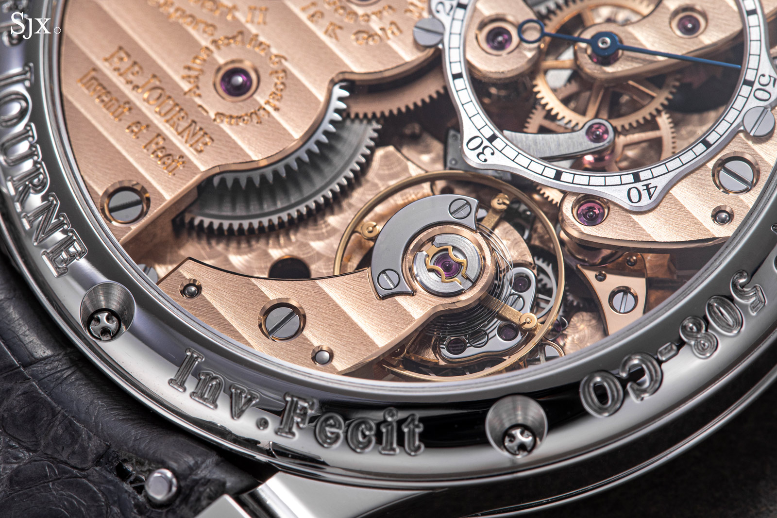
A free-sprung balance relies on either screws or weights (masselottes in French) on its rim. By moving the mass centres of the screws or weights further apart from the balance’s axis, the total moment of inertia increases slightly and the balance slows down. Bringing the weights towards the axis of rotation diminishes the inertial load and speeds up the balance.
A free-sprung architecture is preferred over a stud regulator because it preserves regulation better. While a friction-fitted stud might move fractionally if the watch undergoes a shock, a weighted balance suffers no movement in its components. The system is generally thought to be more prestigious and is costlier to manufacture and regulate, but at the same time much more stable. For example, the Poinçon de Genève hallmark stipulates that a movement needs either to have a free-sprung balance or a reliable means of locking the regulating stud in place (like a swan’s neck regulator for example), in order to be eligible for the certification.
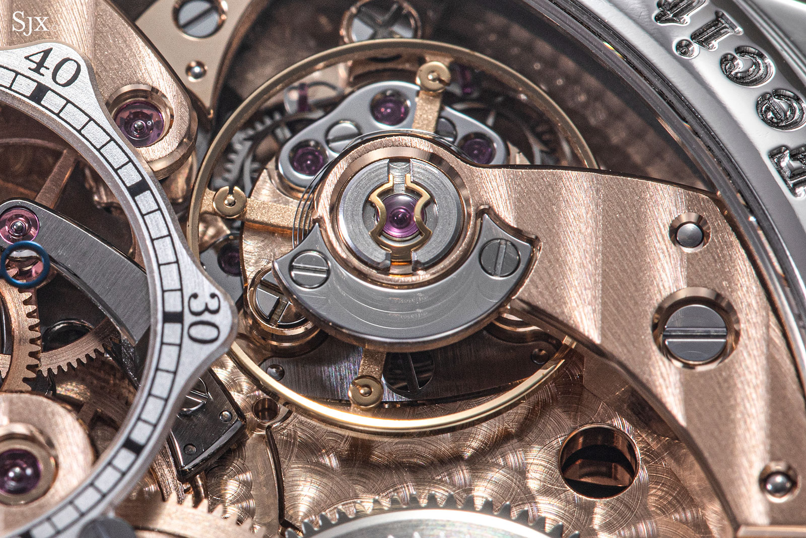
The Chronomètre Optimum balance is also among the select few Journe timepieces to feature a Breguet-Phillips overcoil hairspring. A Breguet overcoil refers to the outermost coil of the hairspring which is raised and abruptly bent over the others. The utility of such an overcoil is that it ensures a concentrical “breathing” of the hairspring, that is all coils expand and contract evenly, which keeps the centre of mass centred on the balance axis. In turn, this makes the oscillating system less vulnerable to positional errors and more isochronal.
This type of end curve was adapted for flat hairsprings by Breguet, from John Arnold’s cylindrical hairsprings. Later on, the subject was analytically studied by the mathematician Edouard Phillips, who devised a formula for reliably modelling and bending a theoretically perfect overcoil.
One might ask why don’t all F.P. Journe timepieces feature such an end curve. The answer is fairly straightforward: a Breguet overcoil demands generous vertical space, which not all Journe calibres are able to provide. Equally, Phillips showed that such an overcoil is more effective for longer hairsprings and larger balance wheels. Also, in comparison to watches from other makers ranging from Rolex to Voutlainen, the average F.P. Journe balance is rather small, so the overcoil’s utility is somewhat diminished.
Concluding thoughts
The F.P. Journe Chronomètre Optimum is undoubtedly a complex timepiece. Amusingly, the sheer wheel count is higher than that of a classic chronograph complete with clutches and counters. Observed through the case back, the movement feels substantial, dynamic and high performing.
Distilled from Mr Journe’s vision of a perfect chronometer, the watch certainly is meant to be a purist’s timepiece, albeit not a perfect one. The movement performance is perhaps hampered by its own over-engineering and reveals Mr Journe’s predilection for complexity, particularly in the EBHP.
A timekeeping instrument
The EBHP is a strong fit for this particular timepiece, but due to its sophistication, unsuited for a wider use across other F.P. Journe models. A simpler escapement could be implemented across the catalogue to enjoy economies of scale, like how the Voutlainen natural escapement is found in all variants of the Vingt-8 movement, but that is just not how Mr Journe does things.
Overall, the Chronomètre Optimum is a very unique and appealing take on modern chronometry, subtly paying tribute to clocks of old. In fact, the Chronomètre Optimum would fit comfortably in on an exhibition of precision instruments alongside marine chronometers, rather than in an exhibition of high horology wristwatches.
This was brought to you in partnership with F.P. Journe and The Hour Glass, the F.P. Journe retailer in Southeast Asia and Oceania.
Back to top.

