Insight: The Ingenuity of the F.P. Journe Centigraphe
A very different and very clever chronograph.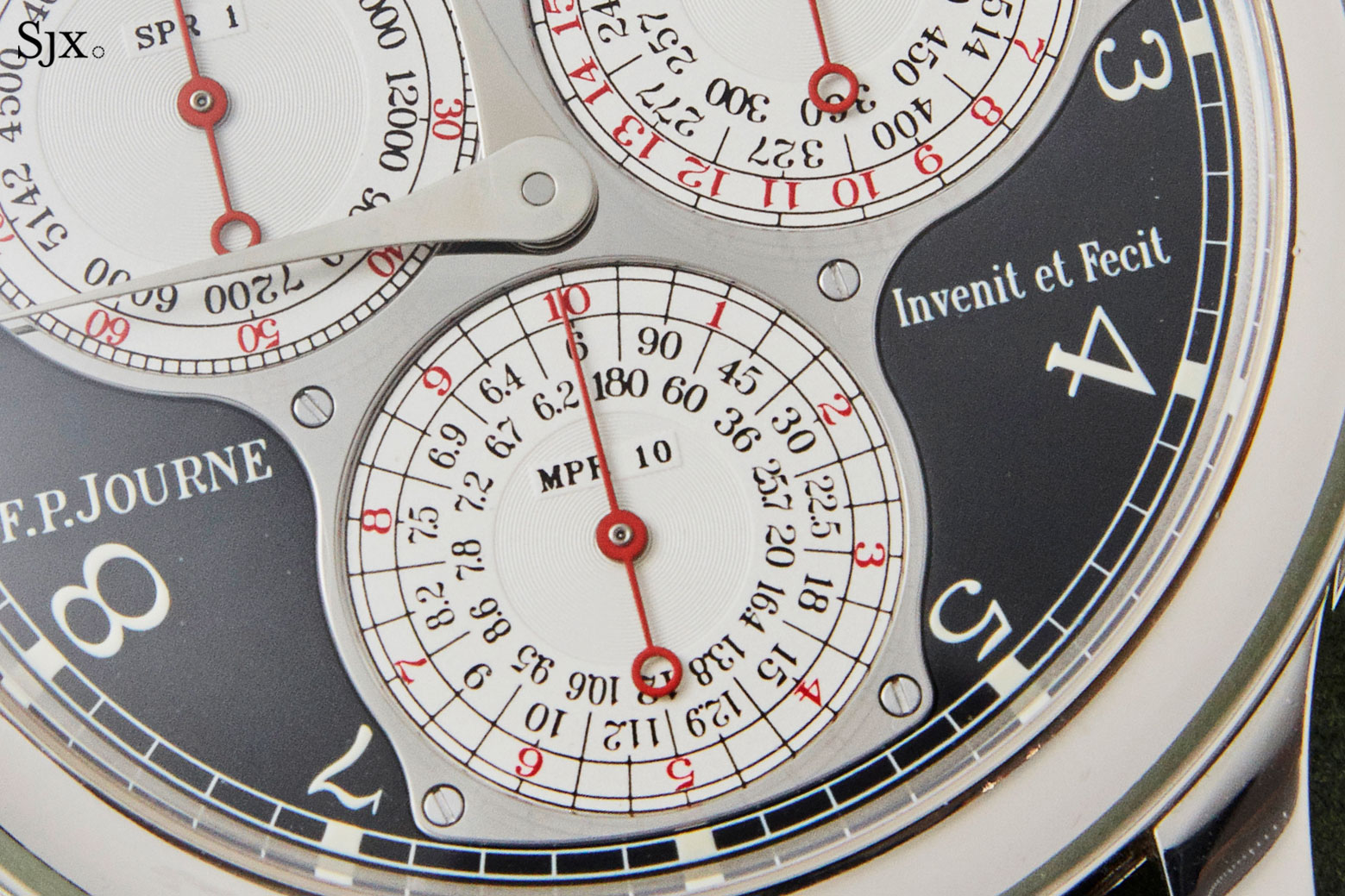
Modern mechanical chronograph movements have mostly been conceived according to two standardised recipes. One is the vertical clutch approach exemplified by the the sporty, performance oriented cal. 4131 inside the Rolex Daytona, while the other is the classical, lateral coupling architecture used by the celebrated L951.1 in the Lange Datograph.
Sticking with a successful architecture is no bad thing, after all, chronographs are complicated enough in their basic form. However, there are some chronographs that stand out for being truly original, like the F.P. Journe Centigraphe and its cal. 1506. Constructed like no other chronograph on the market, the Centigraphe seeks to measure times with a resolution of 1/100th of a second with a unique movement that is modern in its approach yet subtly references the work of John Harrison. In many ways it encapsulates the philosophy of François-Paul Journe, which prizes original, creative watchmaking that pays tribute to historical greats.
The cal. 1506
Despite its achievements, the Centigraphe is overshadowed by the brand’s signature watches, namely the Resonance and Tourbillon Souverain, and remains one of of F.P. Journe’s less-known offerings. Paradoxically, the Centigraphe should be more recognised than most other F.P. Journe watches because has a tangible link to the world of celebrity with its Formula 1 provenance, having been conceived at the suggestion of Jean Todt, the former boss of Ferrari’s Formula 1 team. Although often overlooked in favour of its more famous relatives, the Centigraphe remains one of the most ingenious watches invented by Mr Journe.
The secret of the Centigraphe lies at its centre
In a nutshell
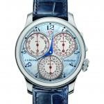
The Centigraphe was invented to to measure elapsed times with a resolution of up to 1/100th of a second, or 0.01 seconds. Its dial features three registers for that purpose.
The first counter (top left) keeps track of the hundredths of a second with a foudroyante seconds hand that makes one revolution a second; next to it (top right) is the seconds counter that registers seconds in 20-second blocks, and the last counter (bottom) keeps track of elapsed minutes in 10 minutes’ segments.
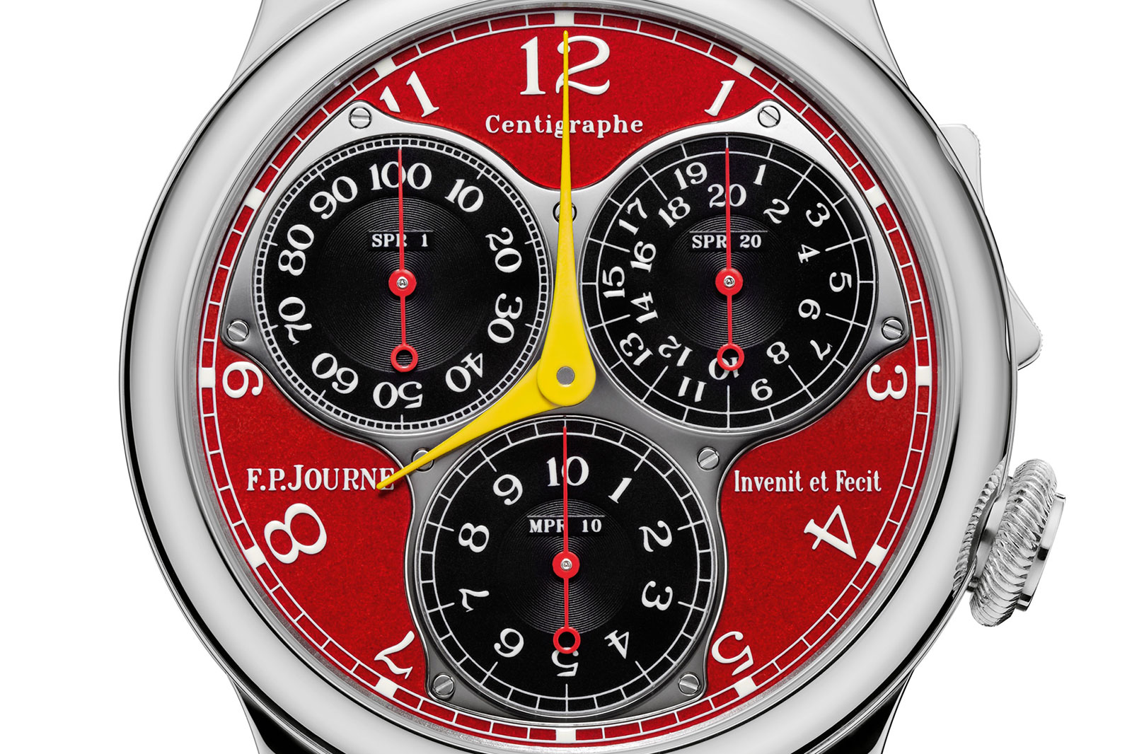
The labels on the registers are short for “seconds per revolution (1)”, “seconds per revolution (20)”, and “minutes per revolution (10)”
The unconventional dial layout is matched with an equally unusual rocker-style pusher located between two and three o’clock – and it is unusual enough that the rocker pusher itself has been patented by F.P. Journe. And because the pusher is where it is, the crown can be found at four o’clock.
Continuing the theme of the unconventional is the movement. It features a barrel that can “rotate both directions” according to the patent, along with a foudroyante hand that is rockets around its register once a second in order to record hundredths of a second. How does all that work? Is it even possible to have a barrel that unwinds in two directions? And how does a low frequency, 3 Hz balance wheel deliver such a fast moving seconds?
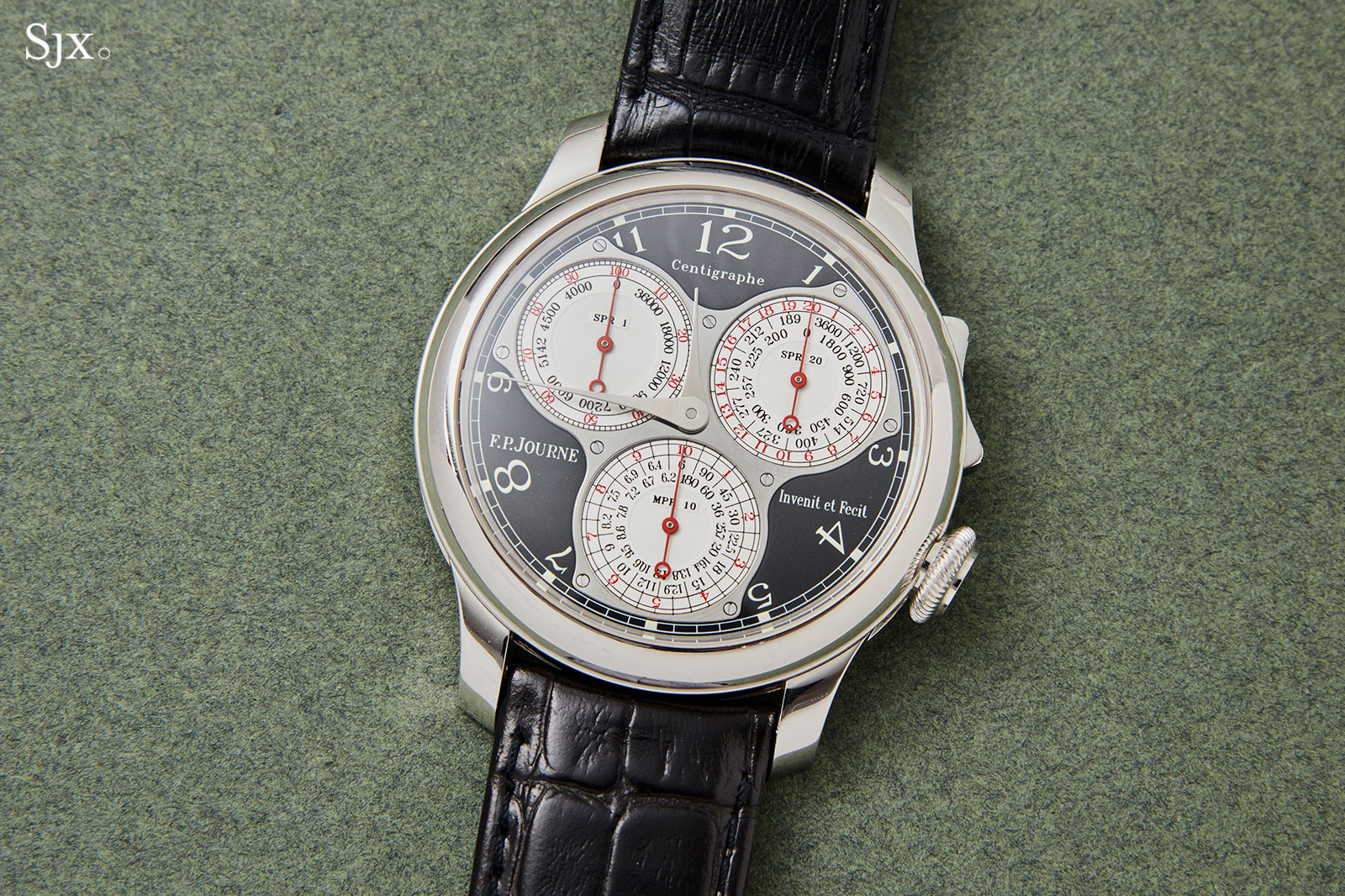
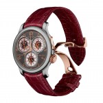
A Centigraphe Black Label
The unconventional operation of the movement can be attributed to a pair of smartly designed systems: first, the coupling device for the 1/100th-of-a-seconds hand, and second, the central barrel that puts everything in motion. Both are elegant and clever, reflecting the talent of their inventor.
Using European patent EP1978424A1 filed in 2007 by F.P. Journe, I explain the Centigraphe by dissecting these systems to explain how they work.
A central barrel and complex winding
The Centigraphe’s barrel sits right in the centre of the movement, allowing it to unwind both through the barrel drum and arbor, at both ends so to speak. This concept wildly differs from traditional barrel constructions that keep the arbor locked in place while the barrel drum slowly revolves around it.
But this central barrel is crucial to for the Centigraphe’s 1/100th-of-a-second trick to work, since the chronograph train requires its own power source that has absolutely no link to the main gear train (we’ll find out why later on). A more conventional solution would have been a second barrel independent of the primary mainspring, but that would have required substantial additional space.
Mr Journe instead opted for a single, large barrel linked to a clever system that permits the arbor to unwind under the action of the coiled mainspring in order to engage a separate gear train, outlined in fig. A. This takes place without affecting the primary, timekeeping gear train. As simple as this may sound, the construction leads to a number of issues that need to addressed, the most important of which being winding the barrel.
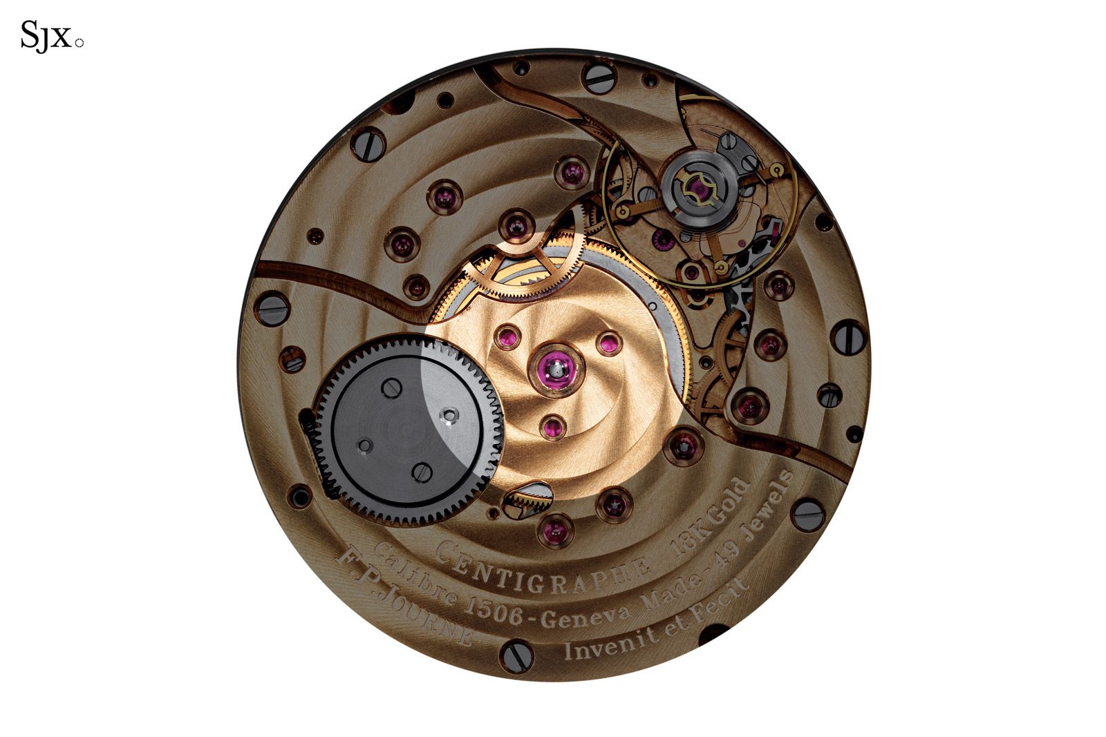
Fig. A: the barrel is right in the middle, with the rest of the movement encircling it like a donut
Since Adrien Philippe’s groundbreaking innovation known as the keyless works (though he is probably better known for founding Patek Philippe), watch movements mostly feature a keyless winding system made up of a castle pinion fitted co-axially on the winding stem which engages in a 90° angle with a larger gear known as the crown wheel. The crown wheel then engages with the click wheel that is connected to the barrel arbour to wind the mainspring.
In a conventional watch, the default, or “0”, position is with the crown flush with the case, so the wearer can easily wind the timepiece by simply turning the crown since all the above parts are constantly in engagement.
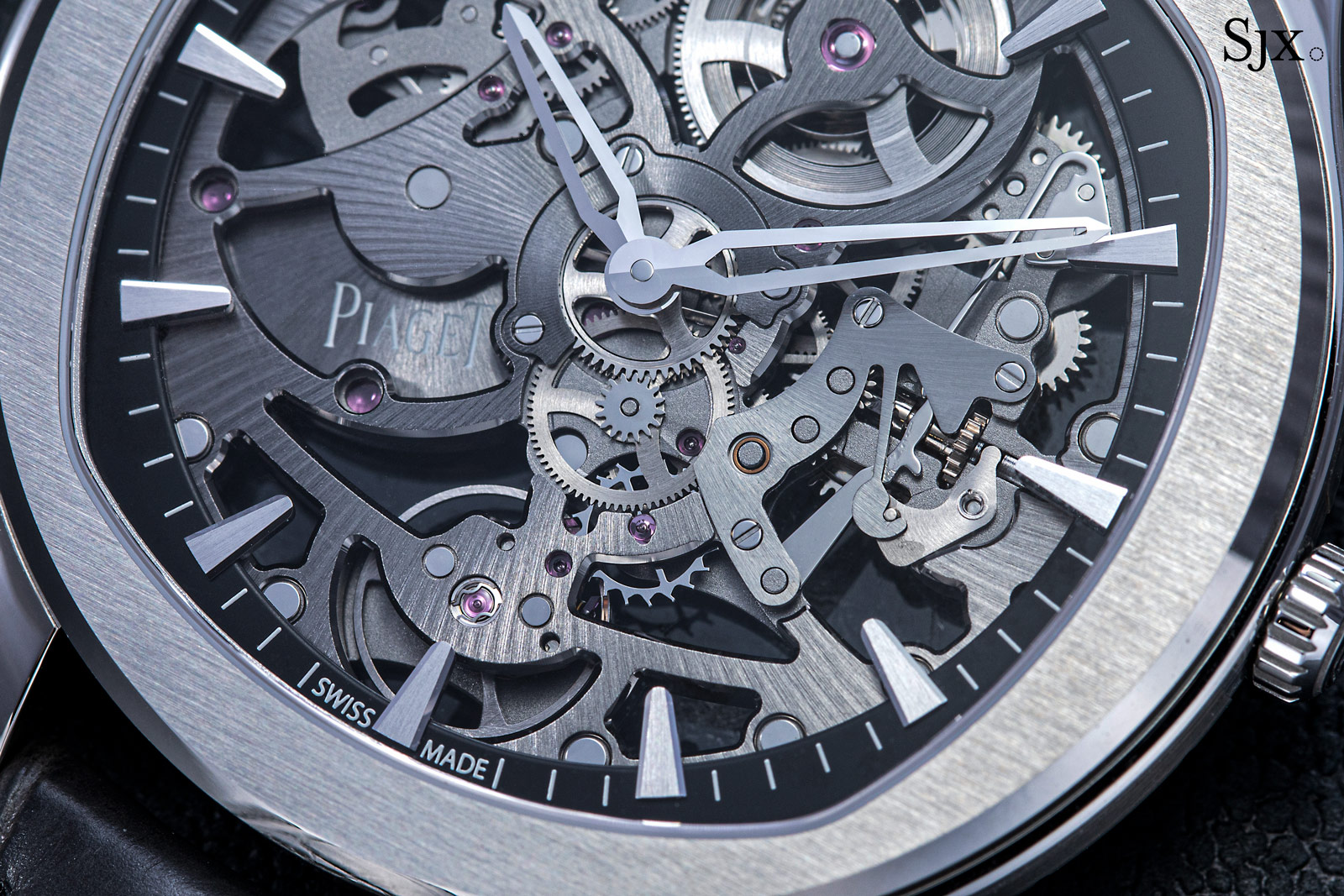
A typical keyless works, exposed here in the Piaget Polo S Skeleton
Returning to the Centigraphe, this traditional arrangement may prove problematic when the chronograph is running because the chronograph acts all the way back to the winding stem, effectively turning the crown. To mitigate this issue, the Centigraphe has a neutral position with the winding system disengaged when the crown sits flush with the case. To wind the Centigraphe, one needs to pull the crown out to the first position. And then setting the time requires another pull out to the second position.
While the neutral position for the crown is a clever and straightforward solution, there remains the possibility that the watch is wound while the chronograph is running. Mr Journe could have taken the easy way out and implemented a blocking mechanism that would lock the crown when the chronograph is engaged. That would have been a mechanically simple solution but it would have restricted the wearer’s interactions with the watch.
A more sophisticated solution would be to maintain the chronograph’s operation during winding, which is naturally the solution adopted for the Centigraphe. To accomplish that, he took inspiration from an older system: the fusee and chain. While the subtleties of this system are many, one aspect is of particular relevance – the wrapping of the chain around the fusee after the barrel has fully run down. In order to do that, the fusee needs to rotate in the direction opposite to that in which it usually interacts with the gear train. It requires the fusee to disengage from the gear train and then a reset of the time indication.
John Harrison, the great English clockmaker responsible for the legendary H4 marine chronometer, is credited with inventing the fusee maintaining system, a clever device which would temporarily keep the gear train running during the period the fusee was being rewound. His invention was essentially scaling down the maintaining-power mechanisms that were (and still are) found in large clocks ranging from longcase clocks to tower clocks.
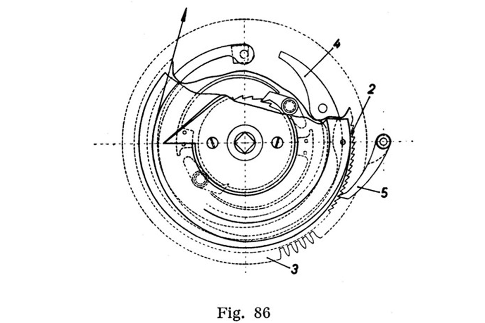
Harrison-style fusee maintaining power mechanism. Image – Théorie générale de l’horlogerie, Vol. 1, Léopold Defossez
A similar device is used in the Centigraphe, no doubt illustrating Mr Journe’s high regard for the great historical watchmakers. The F.P. Journe patent elaborates on a barrel capable of unwinding both ways, complete with a maintaining device.
Before we delve deeper into the subtleties of the Centigraphe barrel, we first need a general understanding of its construction. The cross-sectional diagram below is a reproduction of the fig. 5 from the patent concerning the Centigraphe. It shows the mainspring coils before the mainspring is wound up.
The oversized arbor (in green) has a wide middle section that connects to the mainspring 6.The barrel cover is free to pivot around 1c. Portion 1e has a square section and mates rigidly with the click wheel 8 (purple), which is in engagement with a crown wheel (not shown). Finally, section 1d is the arbor’s axle, which supports the entire barrel assembly and pivots in oversized jewels fitted in the mainplate and bridge.
The lower cradle-like part (red) is the barrel drum 1f, which sports teeth on its lower edge 1a. Back to the barrel cover (yellow), which has an extended lip on its edge (1b) that overlaps the barrel drum and also features teeth mirroring 1a.
In conclusion, the two barrel parts, cover and drum, are independent (as of now) from the arbor and from each other. The large mainspring 6 is connected in the usual way to both the arbor and casing 1a.
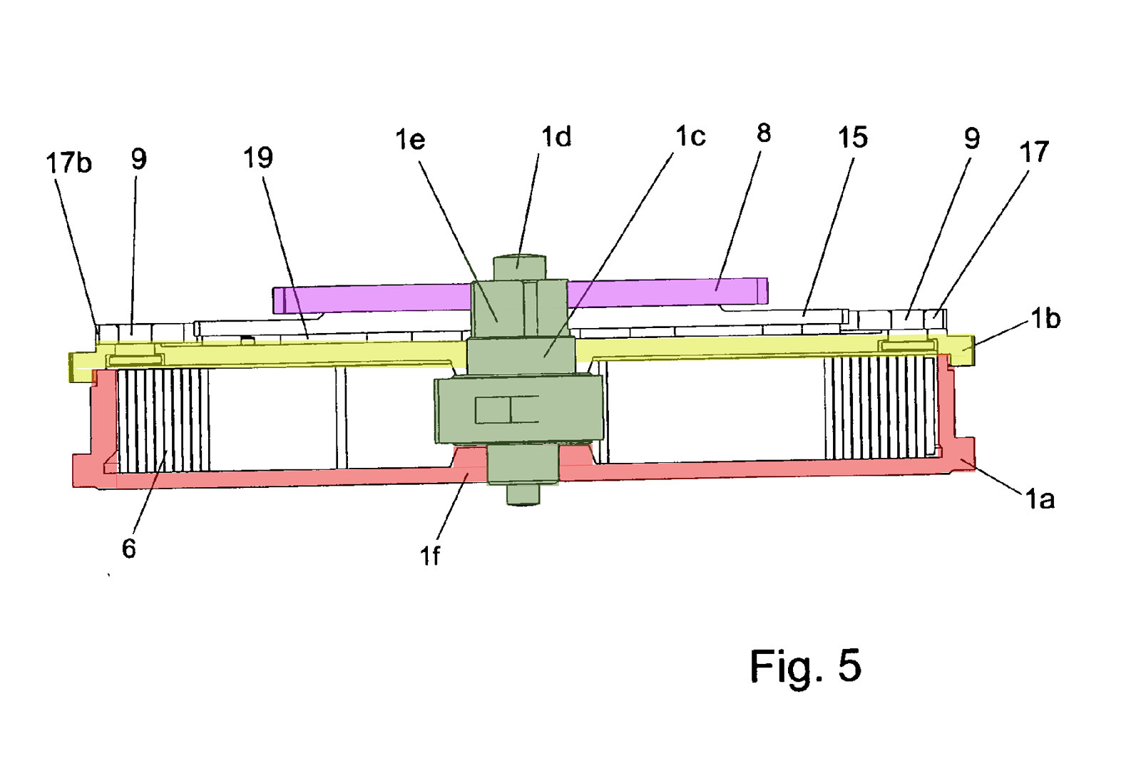
Image – patent EP1978424A1
The trick of having a barrel that unwinds at both ends lies in the opposite directions of the motion of the twin revolving parts. The mainspring is connected to both the barrel and arbour in a traditional fashion, so it forces the two elements to spin in different directions. The unwinding through the barrel drum 1a is conventional, while the rotation of arbor 1c is highly unconventional. This poses the question of how can such a barrel be rewound when both ends are engaged to their respective wheel trains?
An important aspect lies in the going gear train that is linked to the teeth 1a (consequently to the barrel drum, as is convention), while the chronograph train is linked to the teeth 1b on the barrel cover. We haven’t yet established how the barrel cover engages with the arbor 1c, as they are loosely connected.
And so the answer lies in a clever contraption, ressort à préarmage (which translates as “pre-winding spring”) that acts as a sort of a buffer spring between 1c and 1b. At the same time, this spring acts as a temporary energy source for the chronograph during winding.
The reproduction of fig. 4 from the patent shows another perspective of the barrel assembly, seen from above. The overall form and layout are reminiscent of the Harrison-style fusee maintaining system detailed above.
We can observe familiar elements from fig. 5: the central arbor (green), and the outermost set of teeth belonging to the barrel cover (1b in fig. 5).
But fig. 4 also reveals new elements. There’s a gear 15, two set of clicks 16 that are fixed to ring 17, itself engaged to click 18. Wheel 15 is located under wheel 8, both rigidly connected to the central square arbor section. The wolf’s teeth of wheel 15 engage with a pair of clicks 16 and consequently with the entire ring assembly 17.
When the arbor rotates in a counterclockwise manner, driven by the mainspring, it turns ring 17, through wheel 15. Four pillars 9 (yellow), stand raised from barrel cover 1b. They fit in elliptic apertures in ring 17, so as to allow a certain degree of freedom between the two. When wheel 15 interacts with ring 17, the pillars 9 bank inside the sections 10, effectively pushing the entire barrel cover and consequently powering the chronograph train.
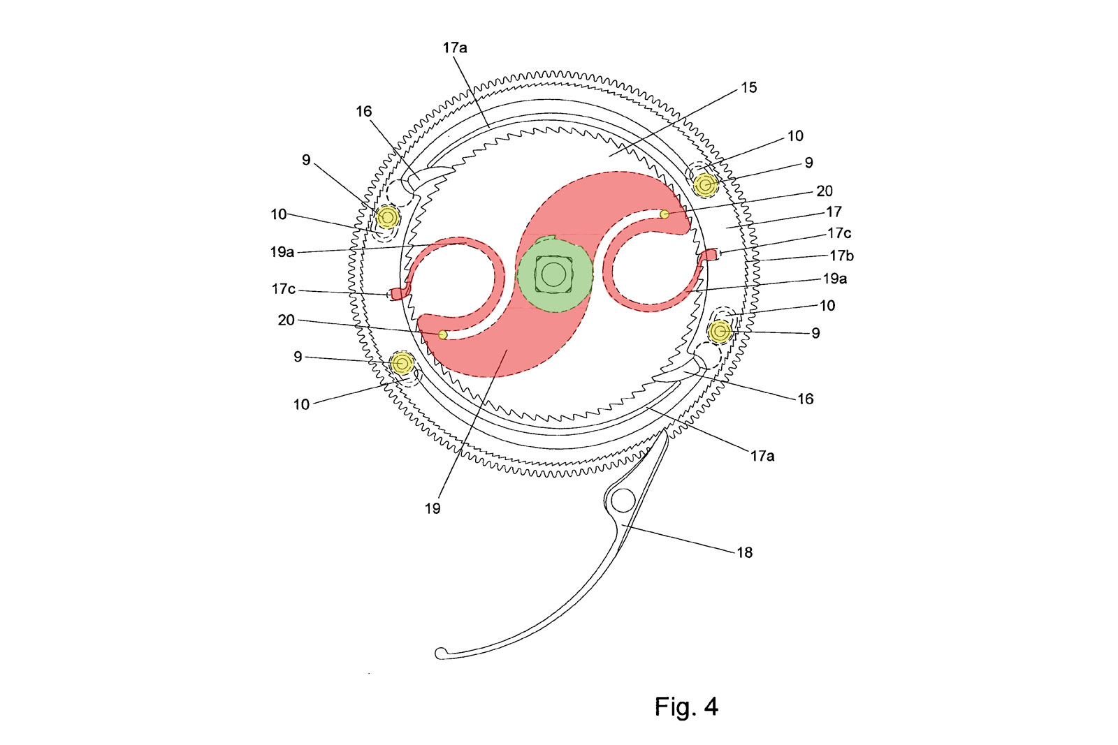
Image – patent EP1978424A1
We haven’t touched on what happens if the wearer winds the Centigraphe when the chronograph is running.
So far, we have established it’s necessary that the barrel cover spins in a counterclockwise direction so as to interact with the chronograph gear train. Should the watch be wound while the chronograph is running, the barrel arbor turns clockwise and since the ring 17 is not allowed to follow along (due to the click 18 that only permits movement in a counterclockwise direction, acting on a set of very fine wolf’s teeth on the ring’s edge), wheel 15 disengages with 17, slipping through a pair of clicks 16.
There’s a novel component that maintains the barrel cover’s movement, the large, curved spring 19 (red). This auxiliary spring pivots independently around the arbor. It engages ring 17 through the two notches 17c and hooks around the pillars 20 (yellow) that are raised from the barrel cover, thus creating a secondary link between the two.
During the time when the arbor turns counterclockwise, engaging ring 17 in the same direction (and subsequently the barrel cover), the elastic ends of the spring 19 are compressed between the notches 17c and pillars 20, storing potential energy. The moment the arbor disengages with the ring 17, the curved, sprung ends of 19 tend to return to their relaxed state, grappling in the notches 17c to push the pillars 20 (and thus the barrel cover) counterclockwise, for as much as the sections 10 allow studs 9 to travel. In this way, the running of the chronograph is sustained by this auxiliary spring for the brief period during which the user turns to crown to wind the timepiece.
As soon as the winding stops, the arbor immediately reengages with the ring 17, compressing the end springs of 19 and driving the barrel cover. The assembly made up of components 17, 19, and the barrel cover through pillars 20, is known as the ressort à préarmage because the spring arms are automatically re-wound after they fulfil their function.
So, in between the turns of the crown while winding, as the wearer pauses to grip the crown, the ressort à préarmage recharges, ensuring a constant and proper torque to the cover 1b and subsequently to the chronograph gearings. Similar systems are implemented in chain-and-fusee timepieces.
Due to its unusual construction, the barrel has a distinctive tactile feel when being wound, with some Centigraphe owners claiming it is by far the most pleasant winding experience amongst F.P. Journe watches. The winding feel is mainly dictated by the pair of clicks 16 and corresponding springs 17a, an arrangement reminiscent of those found in grand sonnerie pocket watches, so the winding may not feel entirely dissimilar to those old-school clockwatches.
Interestingly, the same set-up is also found in the F.P. Journe Sonnerie Souverain, where the entire strike work and sub-systems draw their power from the barrel arbor instead of a secondary mainspring. Like the Centigraphe, the Sonnerie Souverain has a single large mainspring at its centre.
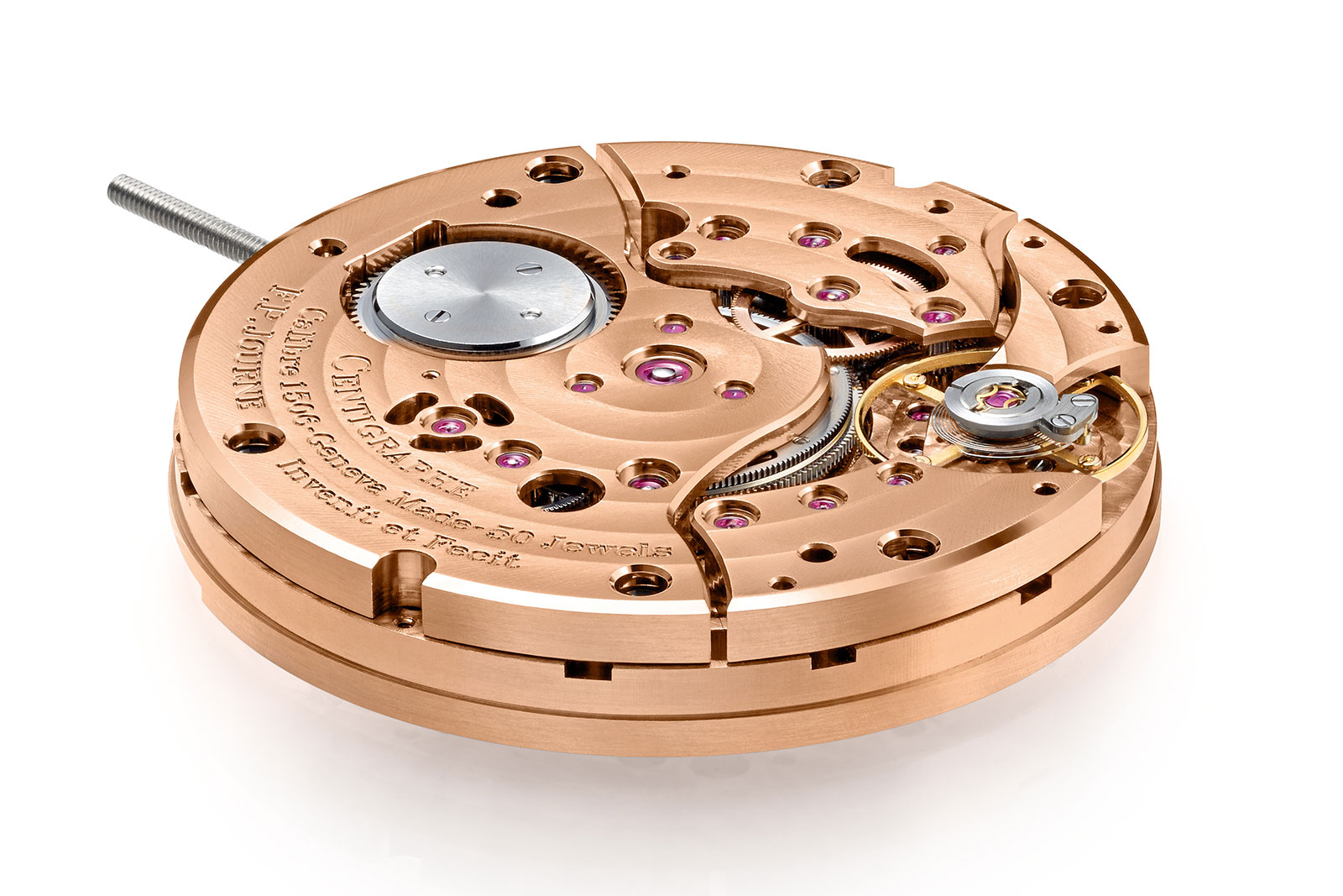
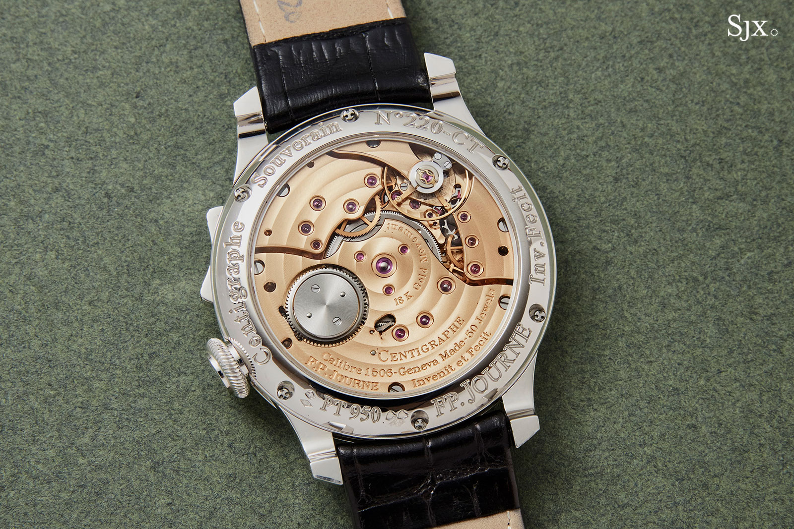
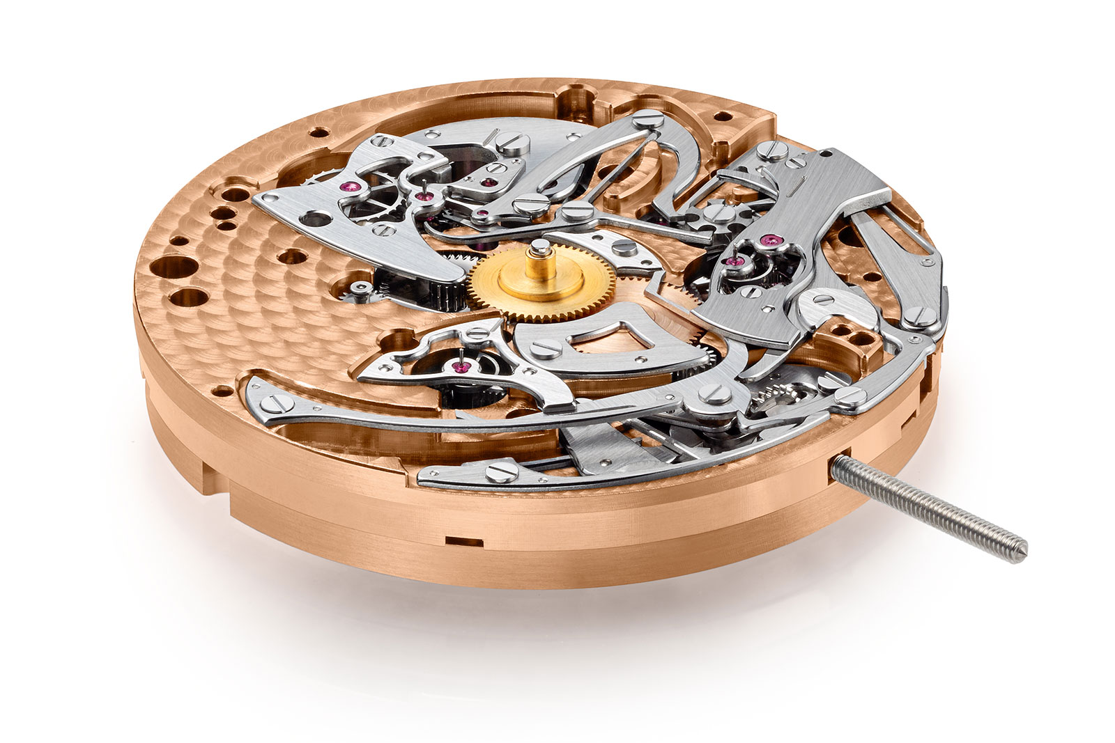
The mechanics of the Centigraphe movement are mostly concealed beneath the 18k red gold bridges. Image – F.P. Journe
The chronograph
As previously discussed, the Centigraphe’s barrel is a particularly complex exercise in ingenuity. Yet it only serves as the motor for the chronograph mechanism.
The majority of traditional, integrated chronograph movements exhibit the chronograph works on the back, so they are visible through the case back. The Centigraphe does the opposite and has all the levers and gears that make up the chronograph under the dial, leaving them invisible to the wearer.
The under-dial view of the Centigraphe movement. Image – F.P. Journe
Chronograph movements can be largely divided into categories depending on the control organ (cam or column wheel) and the engagement system (vertical or horizontal clutches, or oscillating pinion). The Centigraphe is easily defined as a column-wheel chronograph, but when it comes to the engagement type, however, the Centigraphe fails to fall in any of the established categories. Its engagement system borrows elements from both horizontal and vertical clutches, while not being either entirely.
Its very important to note this particular setup not only engages differently, but serves a slightly different purpose than traditional clutches. Conventional chronograph architecture relies on a secondary gear train that couples to the timekeeping train selectively and draws power from it. In the Centigraphe’s case, the chronograph gear train has its own source of motive power (the two-direction barrel), leaving the clutch only to regulate the discharge speed of the chronograph.
Again, in order to understand precisely how all these fine mechanics work, we must again resort to the patent drawings concerning this device.
Firstly, let’s concentrate on the essential chronograph components. Fig. 1.1 below shows the bare chronograph springs and levers in their running state and in an arbitrary position. A keen eye may notice column wheel 23, which interacts with rocker assembly 29 through the click finger 27. The column wheel governs multifunctional levers 30, 31, and 32. Instantly recognisable as well are the three indices standing in for hands of the registers: 4f (1/100th-of-a-seconds counter), 4’c (20-second counter), and 4”b (10-minute counter).
Lever 30 (green) serves both as a clutch and brake lever for foudroyante wheel 4f (yellow). The foudroyante wheel sits at the end of a five-wheel train originating from the centre barrel (drawn with a dotted line in fig. 1). Wheel 4f partially meshes with the large wheel 2 (grey), which is fitted co-axially to the escape wheel of the timing gear train.
The Centigraphe has a 3 Hz regulator, so the escape wheel (which has the traditional 15 teeth interacting with the lever on the escapement’s side) takes five seconds to make a full turn. Since the ratio between wheel 2 and wheel 4f is 5:1, then it is only logical that 4f revolves once every second. The drawing proposes 15 teeth for 4f, which results in 75 teeth in 2.
Conventionally, a pair of meshing gears require the same tooth profiles and pressure angles (the slopes of teeth) in both wheels to ensure a smooth and secure engagement. However, wheel 2 simply serves to regulate the release of power through foudroyante wheel 4f, thus allowing a certain selectivity to their engagement. While wheel 2 advances in definitive ticks, the long, generously spaced teeth of wheel 4f allow it to escape wheel 2’s next tooth in-between ticks. In a way, this implementation resembles that of the star and flirt mechanism found in dead-beat seconds mechanisms. The key to making this design work is to ensure that wheel 4f can accelerate fast enough to jump to the next tooth of a temporarily-stationary wheel 2, before wheel 2 advances forward by the next tick – otherwise there will be noticeable skipping of beats of the foudroyante wheel 4f.
Foudroyante wheel 4f can exist in only two states: engaged or braked. If we refer to fig 1.1 below, we get another perspective on the assembly of 4f. The spring lever 22 (red in both fig 1 and 1.1) connects to a groove 21 in the axle of wheel 4f. The axle pivots between two jewels (the lower one 34) and can slide vertically between the two. Lever 22 can bend downwards and here it is drawn in its relaxed state. Lever 22 only engages with lever 31 via a hard-wearing ceramic or sapphire sphere (blue), which fits into a dedicated hole in spring 22 (as seen in fig. 1.1). Lever 31 can move slightly clockwise, coerced by its return spring 41, if it falls between two pillars of the column wheel.
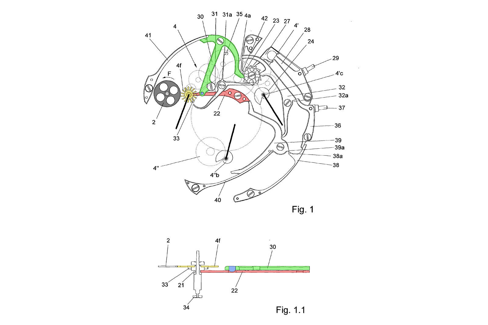
Image – patent EP1978424A1
This action can be seen in fig. 2, which shows the chronograph in its stopped position. As discussed, the column wheel has turned by one tooth, driven by pusher 29, thus allowing one end of lever 31 to fall in-between two of its pillars (purple). When lever 31 moves, the recessed sphere (blue) exits its slot in spring 22, pushing it downwards (fig. 2.1). As spring 22 bends under the pressure, it draws the entire 4f axle downwards, effectively pushing it into the lower jewel 34 (purple). This succession of lever interactions causes 4f to fall out of engagement with 2. The entire 4f assembly is braked agains jewel 34 by the tension in spring 22.
On the dial, the 1/100th-of-a-seconds hand stops in an arbitrary position, pointing to an exact marking along the scale of the register. The braking is strong enough to resist the power still exerted by the mainspring, for the chronograph gearing remains constantly coupled to the barrel.
Having stopped the chronograph, the user reads the elapsed time on the dial and then has two options: restarting or resetting the chronograph.
For the former, he would press the rocker pusher, engaging 29, which would in turn rotate the column wheel by one step; one of its pillars would then push agains lever 31, bringing it back into the position shown in fig.1. The sphere (blue) would fall into its slot, allowing 22 to spring back to its relaxed state, consequently lifting assembly 4f back in engagement with the governing escape wheel 2.
There is potential issue with this clutch construction that can arise when the chronograph is restarted: when arbitrarily stopped, the broadly-spaced teeth of wheel 4f may not perfectly engage with the densely-packed teeth of wheel 2. This may cause premature wear on the teeth and slight “stutter” when restarting, but due to the high speed of the gearing, everything is bound to fall into proper engagement immediately after restarting.
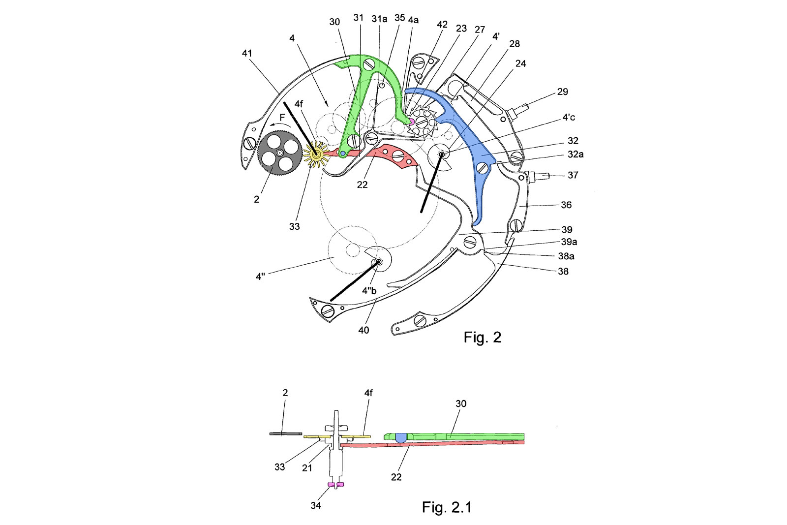
Image – patent EP1978424A1
Resetting the chronograph is a slightly more complicated matter. If we turn our attention back to fig. 2, we can notice the double reset hammer 39 (uncoloured), which is tensioned by spring 40 and kept in place by latching spring 38. Looking closer, the latching between ends 39a and 38a respectively becomes clear. Hammer 39 is also in engagement with lever 32 (blue), which interacts with the column wheel as well. When the watch is reset, the user actuates the rocker part 37, which lifts the detaining spring 38, unlatching hammer 39.
The result, namely the chronograph mechanism after reset, can be seen in fig. 3. Free from its hook, the reset hammer (orange) falls, coerced by spring 40, into both reset snail cams attached to mobiles 4’c and 4”b. Under the action of the hammer, the snail cams rotate to their zeroed position, carrying the hands along with them. At the same time, part of hammer 39 pushes into lever 32 (blue), which consequently pushes into lever 30, eventually causing 4f to reengage with wheel 2.
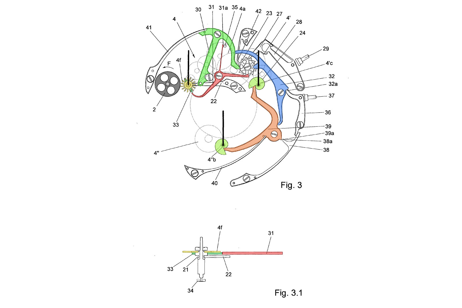
Image – patent EP1978424A1
What stops 4f from running indefinitely is finger 33 (green) fitted coaxially to 4f, which is meant to interact with the stopping lever 31 (red). This stopping lever 31 is controlled by the column wheel.
If we refer back to fig. 1, one end of lever 31 (uncoloured) slots between two pillars of the column wheel, which means its long finger is away from mobile 4f. In fig. 2, the chronograph is stopped and lever 31 is pushed towards mobile 4f, ready to engage in resetting. This lever is designed to incorporate a return spring 31a, simplifying the construction.
As mentioned, finger 33 encounters the detaining part of lever 31 and stops in its run, although it keeps its engaged position to wheel 2. Due to the large spaces between 4f’s teeth and the very short teeth of wheel 2, if finger 33 is angled to stop into lever 31 at a precise moment, wheel 2 slips in-between 4f’s teeth. In this state of pseudo-engagement, wheel 2 continues to spin, ready to reengage with a stopped mobile 4f.
Under the strain from the mainspring, the 4f assembly pushes through finger 33 into lever 31, thus keeping stationary (a close up can be seen in fig. 3.1). Clearly, the hand is mounted on the pinion so it points to the zero marker on its register in the reset state.
When the Centigraphe is started again, a column wheel pillar pushes lever 32 clockwise, which cocks the reset hammer 39 under the spring latch 38, as seen in both fig. 1 and 2.
When handling the Centigraphe, the wearer will notice two peculiarities that stem from its unusual mechanics. First, the 1/100th-of-a-second hand slightly but visibly sinks into the dial when it is stopped, because the entire mobile 4f travels downwards. Second, the dance of the same foudroyante hand performs when resetting is apparent. Instead of instantaneously jumping back like most chronographs, it leisurely travels to the zero position.
As a side note, the Jaeger-LeCoutre Duometre à Chronographe features a foudroyante seconds that functions similarly to the Centigraphe, where its stops in the in-between state of engage. However, the Duometre has no formal restart function since it’s a mono-pusher chronograph, so its mechanics are somewhat different and built only for a traditional reset. The Duometre was unveiled in 2007, close to the Centigraphe’s own release date, but they were surely developed separately.
Also, it’s worth noting the resetting of the other two chronograph hands for the 20-second and 10-minute registers. The mobiles 4’c and 4”b remain in constant engagement with the gears connecting them to the barrel – how is resetting possible?
The respective cams are fitted coaxially to their pinions for the hands, but the cams and pinions are not a single component. The two parts are pressed together by a spring underneath, leaving them otherwise free of independent movement, so the pinions are essentially carrying the cams. Under the strong impulse of the reset hammer, the feeble springs give, allowing the cams to reset and stop, while their associated gears continue moving. This set-up is fairly common in watchmaking and can also be found in the F.P. Journe Resonance, where the twin seconds hands can be reset to zero when the movement continues ticking.
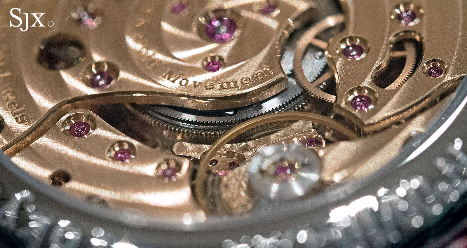
The Centigraphe movement cal. 1506 has 50 jewels within its 34.4 mm (or 15”’) diameter. Since a number of those jewels can be easily observed on the case-back of the timepiece, I took the liberty of highlighting those that map out their respective gear trains in fig. B.
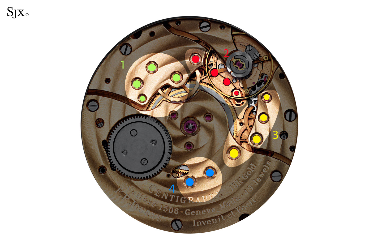
Fig. B: the gear trains of the Centigraphe
Starting with segment 1 (green): the large, overlapping wheel that connects to the barrel cover is the first wheel of the chronograph works. The green points denote the gears that lead to the mobile 4’c, which counts up to 20 seconds.
Segment 2 (red) connects to the first large wheel in segment 1. All these closely arranged gears lead to mobile 4f, denoted by the rightmost red dot that sits noticeably close to the escape wheel.
Segment 3 (yellow) is the traditional going train for the time (train à finissage in French). It connects to the barrel, albeit to barrel drum, not cover. The timekeeping train ends with the escape wheel, which engages the regulator.
Segment 4 (blue) shows the two gears that make up the 10-minute indicator. The leftmost blue dot is mobile 4”b.
Concluding thoughts
Since it was launched, the Centigraphe has been the subject of much discussion about whether it is an accurate timer for 1/100th of a second or merely an amusing gimmick. The claim that it is able to measure elapsed time with such resolution is bold, particularly since the movement beats at a decidedly low frequency of 3 Hz, or 21,600 beats per hour.
The low frequency affects the elapsed time measurement of 1/100th of a second in two ways. One is the slow angular velocity of the wheels, and the other is the noticeable, discernible steps in the movement of the foudroyante hand.
In the Centigraphe’s case, the angular velocity issue is somewhat mitigated by clever gearing and the ability of foudroyant wheel 4f to brake arbitrarily in virtually any position. Interestingly enough, the value of 1/100th of a second is arbitrary in itself, for the measurement depends on the markings of the dial. Based on the one-second run of the hand around the dial, the register scale could have been in sixths, tenths, or 1/50th-of-a-second, and the movement would have registered those just as well.
Secondly, foudroyant wheel 4f’s connection to wheel 2 leads the latter’s ticks being transplanted onto 4f‘s movement. Although the barrel cover and mainspring tend to smoothly accelerate wheel 4f, its engagement with the escape wheel breaks down the fluidity of the motion. The resulting motion is periodically accelerated then decelerated, and then accelerated again. It’s clear that this lack of consistency of motion takes a toll on the accuracy of the 1/100th-of-a-second measurement. A very high frequency movement would be more suited to the task, maybe even the Seiko Spring Drive movement that relies on a flywheel to deliver purely fluid motion in one direction that is not plagued by discernible “ticks”.
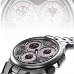
A parallel can be drawn with the Montblanc TimeWriter II Chronographe Bi-Fréquence 1,000 of 2012 that was developed to record elapsed times of up to 1/1000th-of-a-second with the aid of a secondary, 50 Hz regulator (that’s 360,000 beats per hour). However, a 50 Hz balance can only naturally record hundredths of a second, which is incidentally what the Centigraphe strives to do.
In order for the Montblanc to record elapsed times ten times smaller than its natural frequency, it opted for additional gearing to create the “tick” that can be observed every ten segments of 1/1000th-of-a-second. A “homogenisation” wheel (possibly featuring staked and spring-loaded gears) was employed to smoothen out the steps. Whether it succeeded in mitigating the issue is debatable, but at least it tried to address the non-uniformity of a ticking motion. Regardless of its technical achievement, the Montblanc was never successful commercially (in part due to the €250,000 price tag). Few, if any, were actually produced and sold.
The Centigraphe courageously pushes the limits of time measurement, though it remains limited by its fundamental mechanics. While not a reliable 1/100th-of-a-seconds counter, it is more of an academic proof-of-concept contained within an impressively slim case. Is such a precise timer even functional or relevant in practical terms? Certainly not, but it demonstrates the ingenuity of F.P. Journe.
Back to top.