Continuing with our series focused on the mechanical chronograph – we already explained the vertical and horizontal chronograph clutches, along with the advantages and shortcomings of each – we now turn to another vital component but rarely discussed: the chronograph reset mechanism. While the clutch enables energy transmission between the base movement and chronograph, it plays no role in returning the chronograph indicators to a zeroed position. This is accomplished by an altogether separate mechanism that is synchronised with the clutch action but functions independently.
The reset mechanism indexes all the chronograph indicators (hours, minutes, and seconds) back to the zero position, and keeping them securely in place until the chronograph is started once again. Any reset mechanism generally comprises of two main components: a heart cam and reset hammer. The two interact based on clever geometry and illustrates mathematics is often the underlying basis of watchmaking, or more specifically, movement construction.
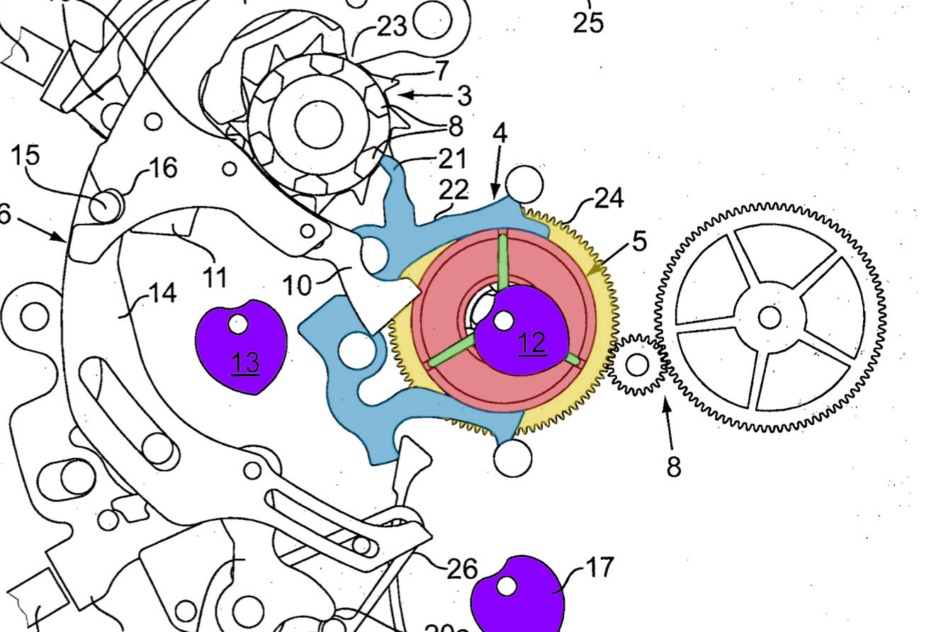
The chronograph works of a Breitling B01 movement, with the reset heart cams (12, 13, and 17) in purple. Image – Breitling patent
The heart cam
Named after its distinctive outline, the heart cam is a seemingly simple component that is in fact the product of some ingenious engineering. While the cam has a turning axis and is a rotational system – in other words, it revolves on a fixed axis – a clear analogy can be made with linear systems. In order to grasp the function of a heart cam, we will start by analysing an equivalent, but linear, system.
Imagine a simple triangle block on a flat plane, as illustrated in Figure I, which can slide freely on the horizontal axis in both directions.
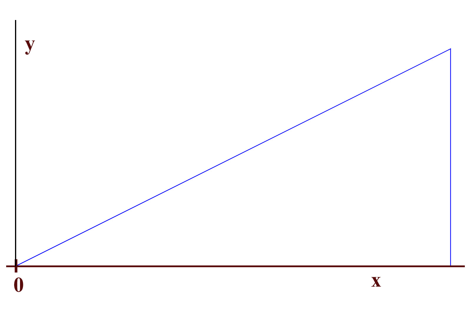
Figure I. A simple triangle on a horizontal plane
If the block is displaced towards the left, as shown in Figure II, an easy and intuitive way to bring it back to its initial position would be to apply downwards force on the slope of the block. Under the influence of the force, the block would tend to move to the right, towards its initial position.
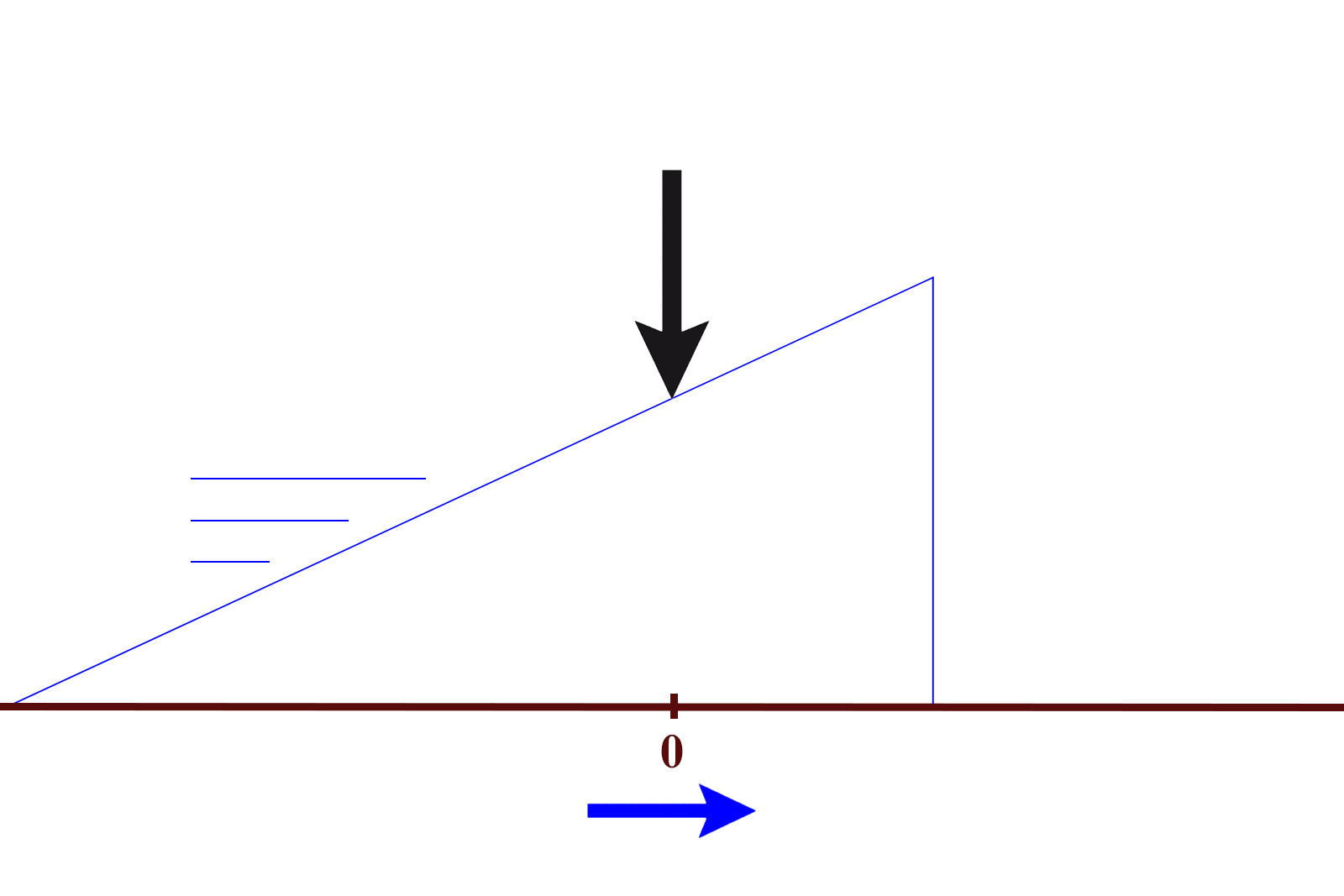
Figure II. Moving the displaced block back to its initial position
Assuming ideal conditions, the block is returned to its zero position when the force acts on its beak until the force can’t displace the block anymore. In a larger and general context this is the basic principle that underlies the Swiss lever escapement.
In Cartesian coordinates, such a slope is described by formula 1. The two coordinates make up a linear function, where y is proportional to x by a given factor a.
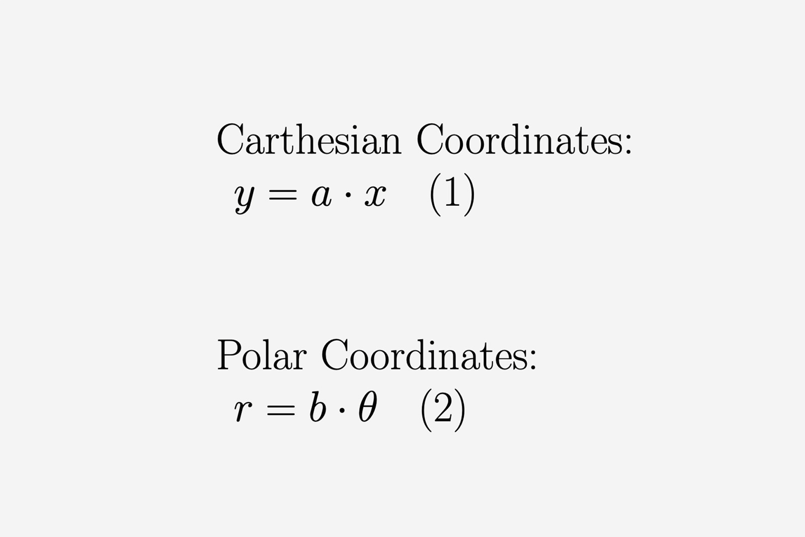
Transitioning to rotational systems, a similar relation can be found in the polar coordinates basis. Instead of linear units, the polar coordinate system employs distances and angles to map out points in space.
For our purposes, we can consider the second equation equivalent to the formula 1, since one coordinate value is directly proportional to the other by a factor in both expressions. Formula 2 actually describes an Archimedean spiral in polar coordinates (Figure III), which is one of the fundamental spiral types. Here we find the spiral is actually a functional equivalent of the slope, adapted for the rotational system.
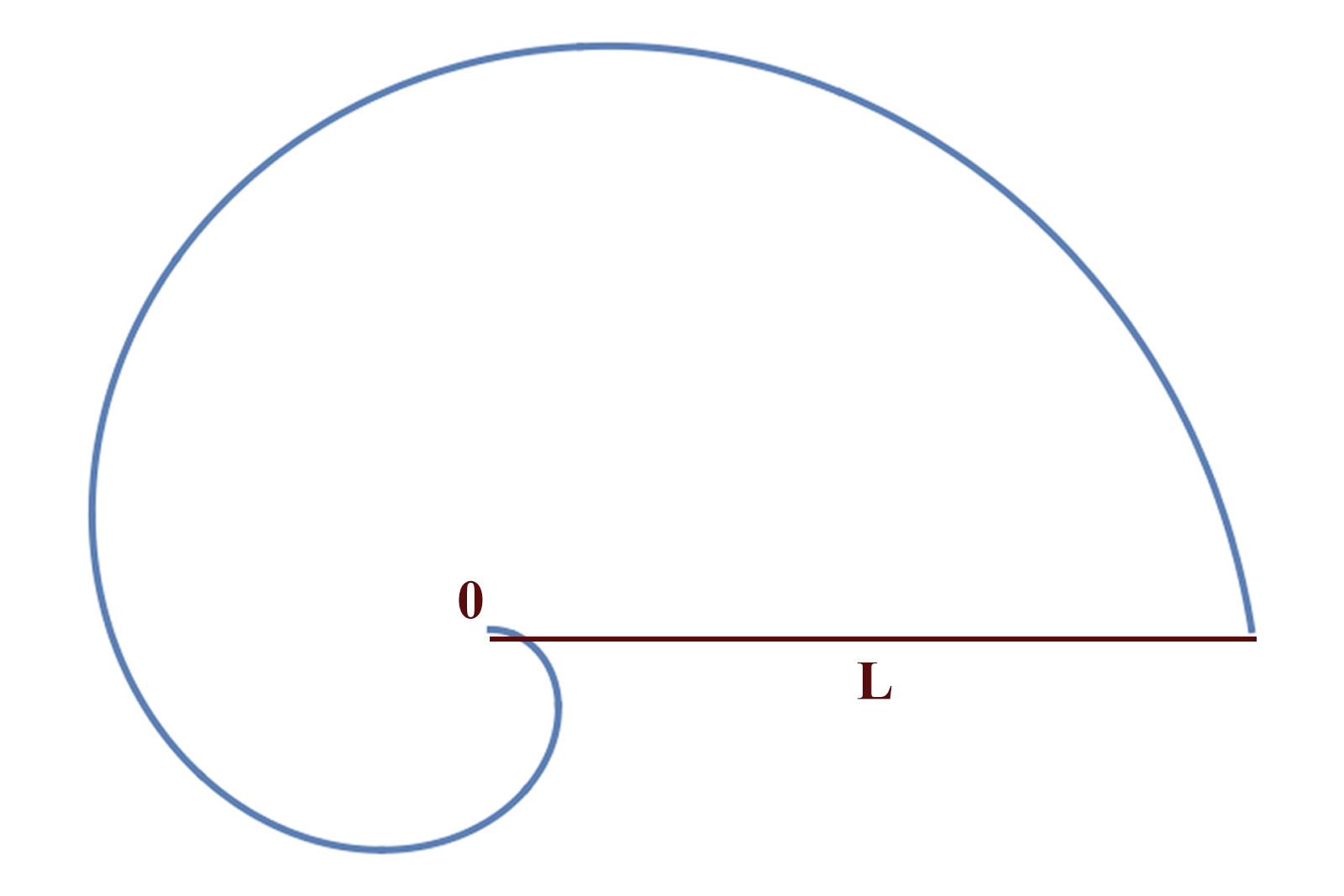
Figure III. Simple spiral with one turn
Suppose a spiral-shaped object is angularly displaced around its origin. Again, it is easy to conclude that some force acting towards the shape’s origin would make said object turn until it reaches its smallest radius — just like it did with the triangle’s beak. This describes the function of a basic snail cam, which is essentially half a heart cam. The geometry brings the cam (and in extension the hand associated with it) back to the zero position (which is the point of smallest radius), regardless of its angular displacement at a given time.
The snail cam, however, has an in-built disadvantage: the reset is always performed in just one direction, no matter the cam’s position. Assuming the reset hammer strikes near the largest radius — which is paradoxically almost adjacent to the smallest radius, thus close to the zero position — the system will make a near-360° rotation to reset. This almost-full turn generates substantial friction and inertial loads on the rotating components, not to mention the requirement of greater force and increased hammer travel in order to make the wide turn. The solution to optimising this is breaking down the spiral into two smaller, symmetrical spirals.
A simple spiral covers 360°, but by breaking it off at 180° and building another that is perfectly symmetrical but developed in the opposite direction, it results in the familiar heart shape cam shown in Figure IV.
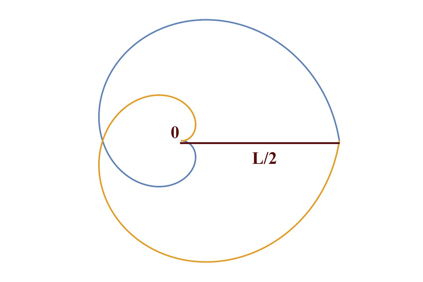
Figure IV. The heart cam is taking shape
The advantages of this set-up are many. For one, the system’s travel during reset is optimised, since the hammer causes the cam to take the shortest route back to zero, steering in either direction, depending on where it falls. We can even go back to our linear analogy and find the equivalent shape in Figure V.
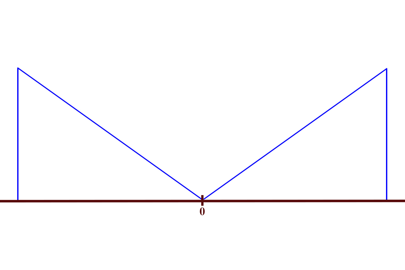
Figure V. The linear equivalent of a heart cam, with two blocks that can travel in either direction
This property optimises the reset of the heart-shaped cam. Assuming the hammer falls near the heart’s peak, it would cause the cam to only make half a turn, instead of the almost-full turn in the case of a simple spiral. Moreover, the maximum possible hammer travel distance is halved, since the largest radius is now only half of the original.
This also makes for a quicker reset, though that is hardly noticeable by the naked eye. Another useful property of this shape is that the acceleration of the cam peaks when the hammer falls, and then the piece gradually decelerates towards zero, so the chronograph hand doesn’t overshoot and halt beyond the index.
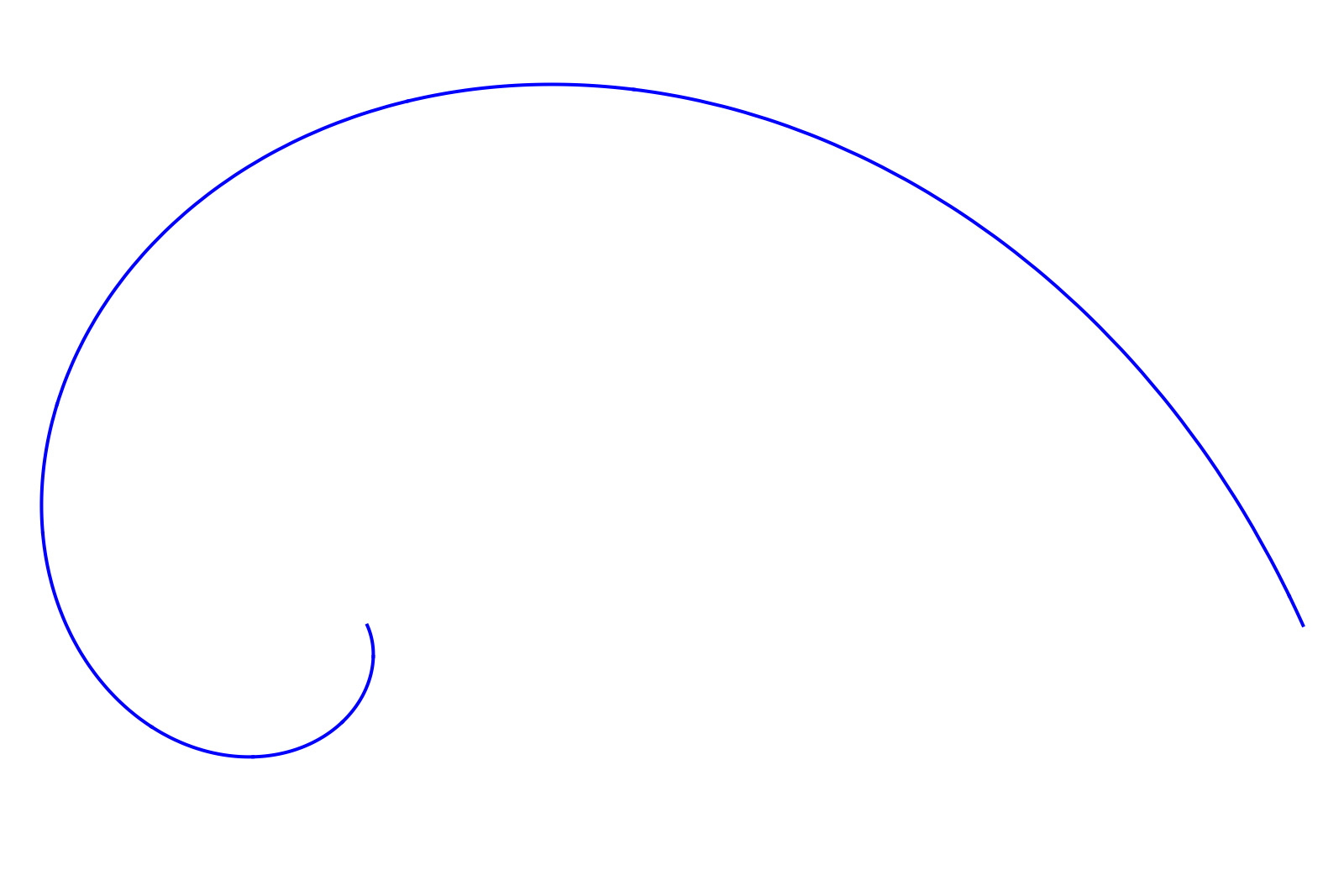
Figure VI. A logarithmic spiral with one turn. Note the more aggressive development, compared to the simple Archimedes spiral
This acceleration-deceleration is intrinsic to the Archimedean spiral, since the transferred torque from the hammer’s force is lowered gradually towards the zero mark as the radius decreases. However, the deceleration is not sufficient in practice, which is why logarithmic spirals (Figure VI) are used for shaping the heart cam.
A logarithmic spiral is mapped by an exponential function. Such a function increases more hastily than a linear one, in our case causing the spiral to develop a little more aggressively, leading to a slightly elongated heart shape (Figure VII) that is very similar to the silhouette of an actual reset heart cam.
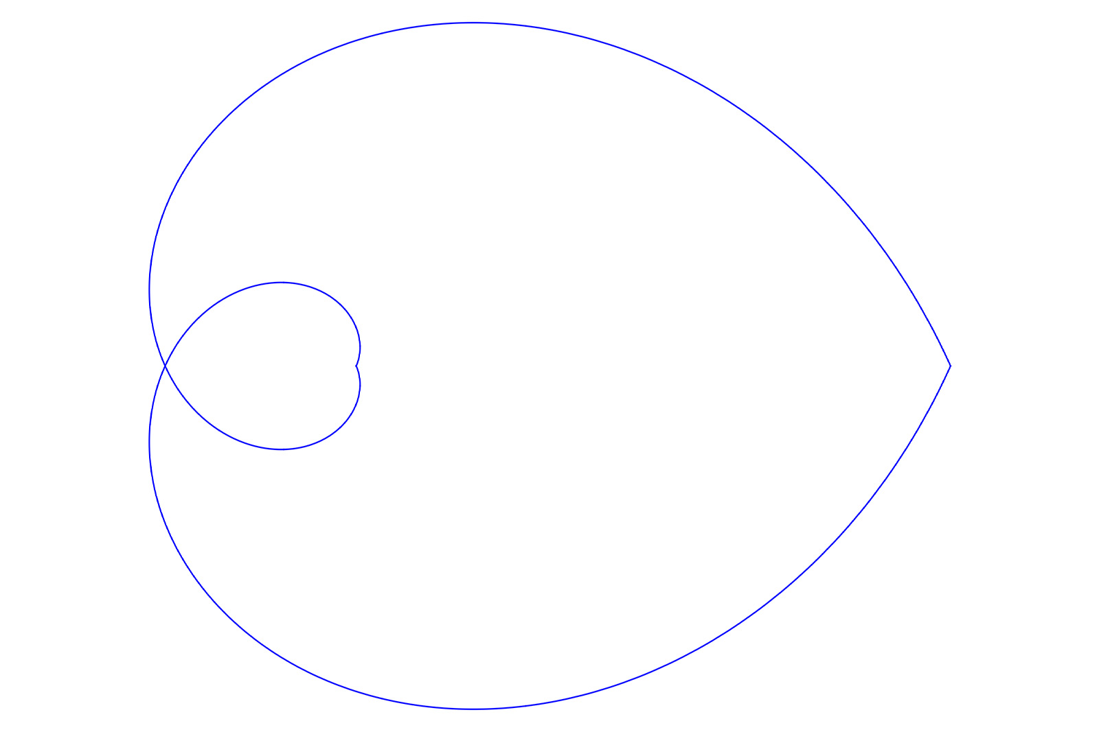
Figure VII. The elongated heart
When it reaches the end of its travel, the hammer must rest on the heart cam in such a way that neither component is prone to any unwanted movement or play. A large notch in the cam assures the hammer settles in an equilibrium position that is stable while also keeping the cam locked securely. Until the chronograph is started, the hammer acts like a brake for the indicators, keeping all the chronograph hands indexed and stationary.
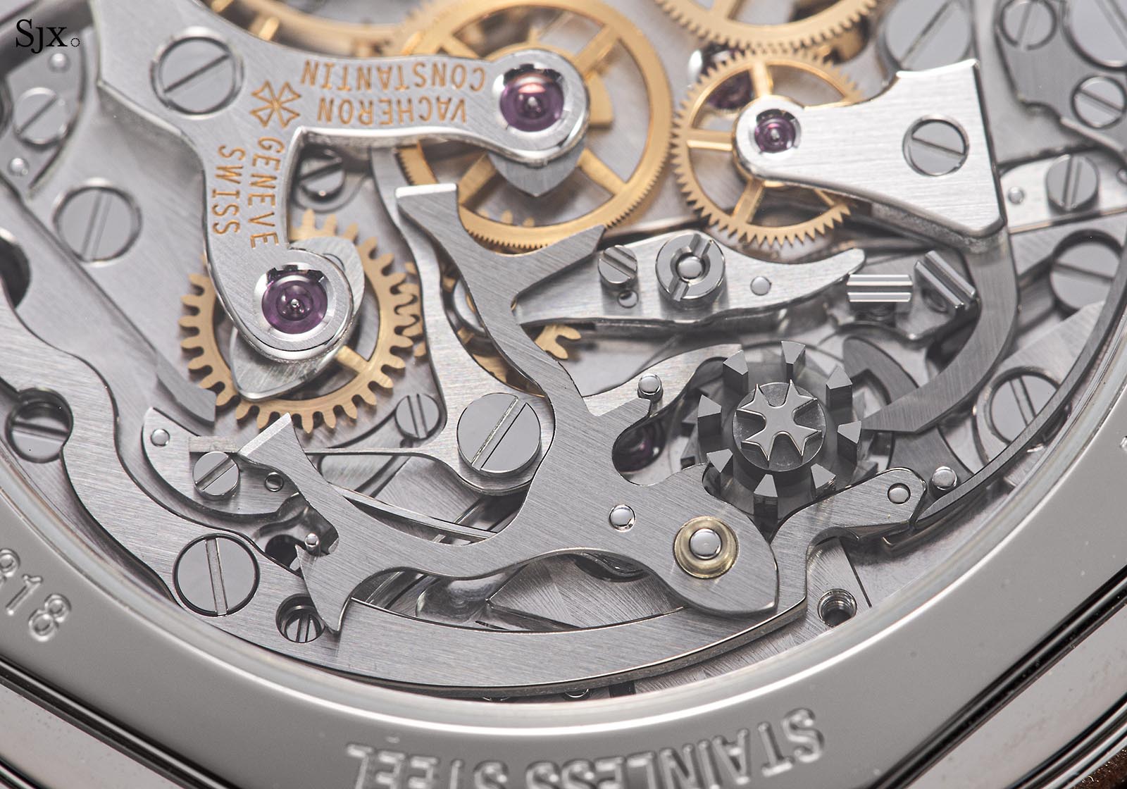
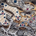
“Elongated heart” cams are visible right under the upper chronograph bridge, each associated with one chronograph hand, here in a Vacheron Constantin cal. 1142
Hammers
The reset hammer is the active part of the chronograph reset mechanism. The head of the hammer strikes the heart cam, causing the cam to turn and index to its zero position.
Hammers are essentially slim levers with wide heads that assure the contact area between the hammer and heart cam is optimised. Hammers are controlled by the chronograph cam or column wheel, cocked or armed by dedicated springs, which assure a consistent, snappy action when resetting the chronograph.
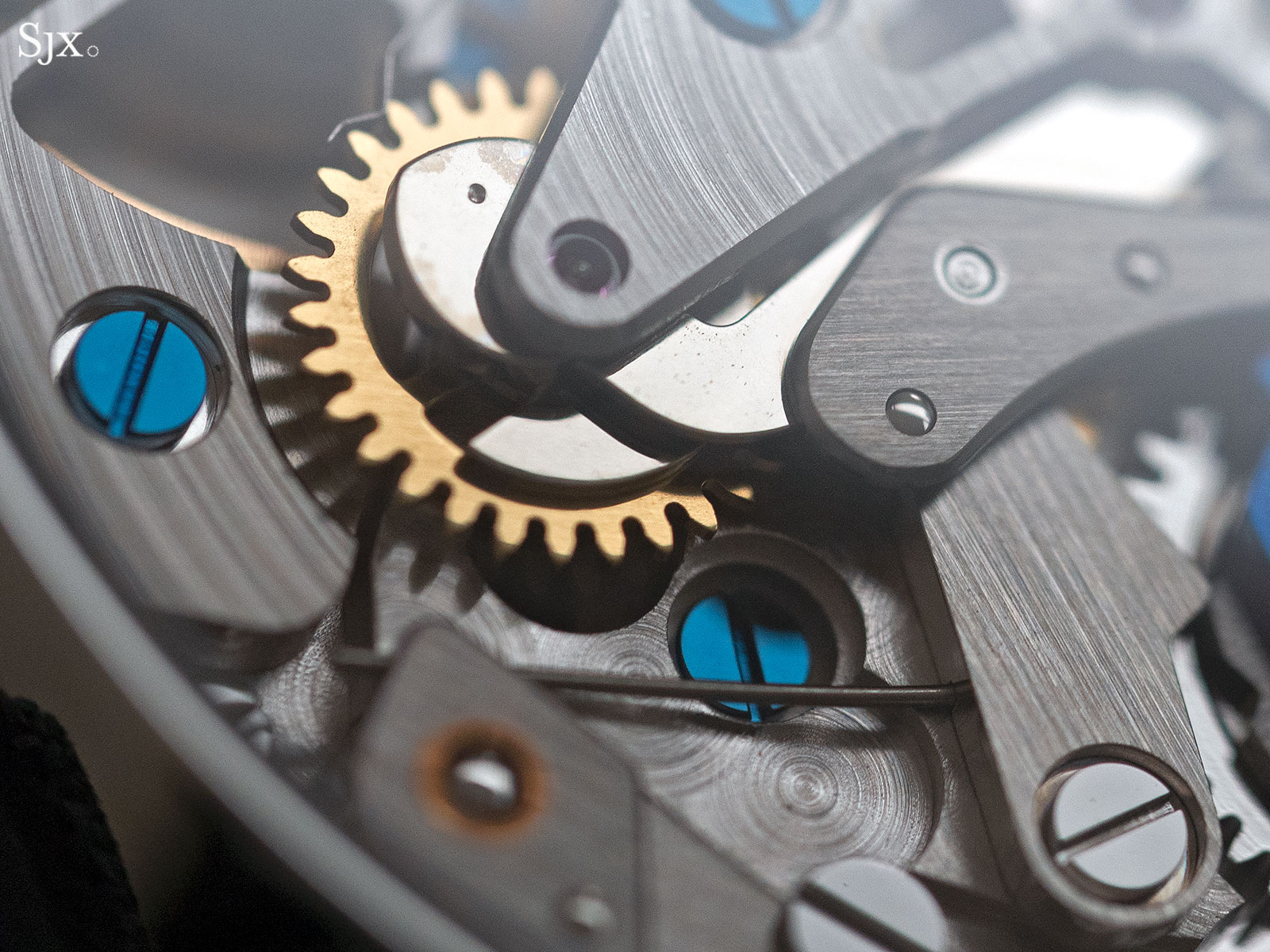
A heart came with its adjacent hammer in the Habring2 A11
A chronograph usually has either two or three registers, and each indicator requires its own head. Most modern chronographs use a one-piece hammer with three heads, an element that was pioneered in the Piguet cal. 1185 and today found in the Rolex cal. 4130 family, amongst others.
Older chronograph movements mostly used a one-piece hammer with two heads for the seconds and minute counters, while employing a separate reset lever for the hour register that is located on the dial side of the movement. The Omega cal. 3861 is a great example, with the arched steel hammer with twin heads clearly visible, while the reset lever for the hour counter is under the dial due to the construction of the movement that separates the hour counter from the rest of the chronograph mechanism.
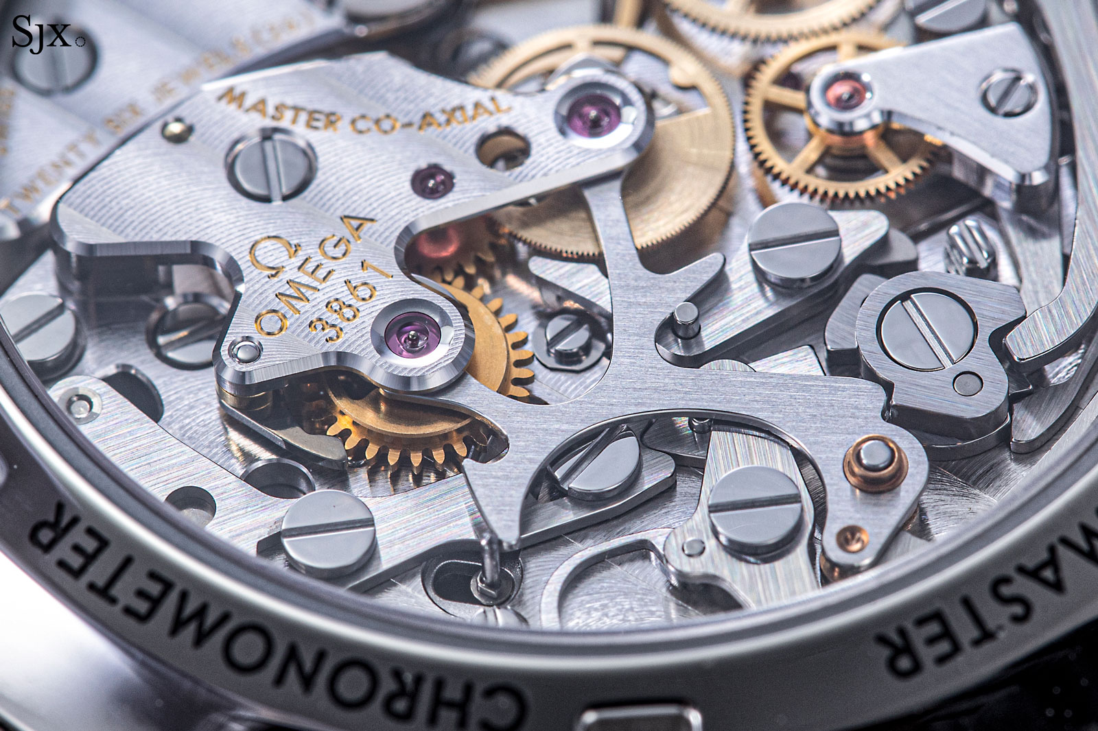
The Omega cal. 3861 in the Speedmaster Moonwatch
Seemingly less fancy than a column wheel or vertical clutch, the chronograph reset mechanism is often taken for granted but nevertheless is a fascinating example of simple and effective engineering based on geometry that is ubiquitous. No matter the sophistication of a chronograph movement, it will inevitably employ a cam and hammer reset system.
The utility of the heart-cam reset is so versatile that it is not only found in chronographs. Any movement that returns a hand back to zero when the wearer activates a setting mechanism also employs a heart cam. The most familiar example of this is the zero-reset seconds that can be found in the Akrivia AK-06, F.P. Journe Chronomètre à Résonance, and Lange 1815 Tourbillon.
Back to top.