In-Depth: Rolex Daytona “Le Mans” Movement Cal. 4132
Exploring the Daytona chronograph architecture.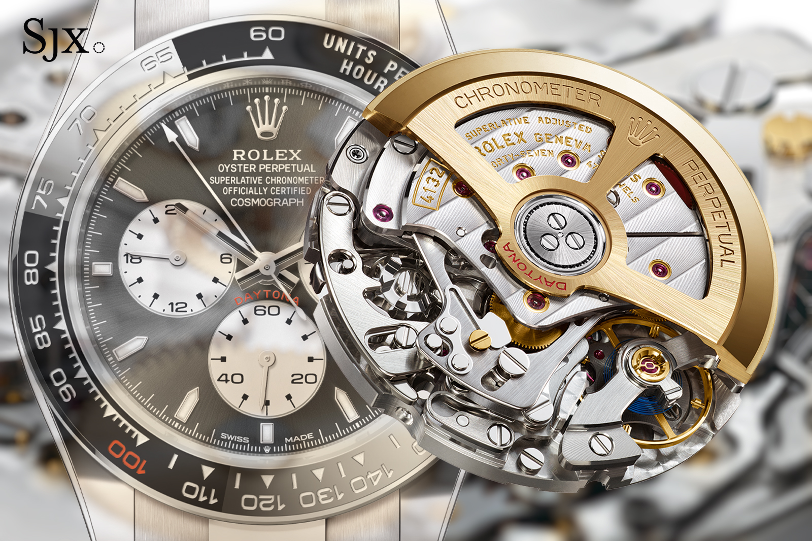
The cal. 4132 inside the Rolex Daytona “Le Mans” is a rare evolution of one of the most revered chronograph movements in modern watchmaking. Based on the long-running cal. 4130 platform, the new movement was developed specifically for the Daytona “Le Mans” unveiled in 2023 to celebrate the 100th anniversary of the famed endurance race.
While visually similar to the cal. 4131 found in current-production Daytonas, the cal. 4132 incorporates a clever mechanical upgrade that allows it to record up to 24 hours of elapsed time. Given the relatively simple upgrade from a 12-hour to 24-hour counter, the cal. 4132 might seem like a weekend project for a brand with the engineering might of Rolex, but the reality is more nuanced.
To achieve this, Rolex engineered a compact differential gear set that doubles the timing capacity without altering the core movement architecture, leaving the movement dimensions unchanged. As with many Rolex innovations, the cal. 4132 reflects the brand’s quiet obsession with functional longevity and serviceability.
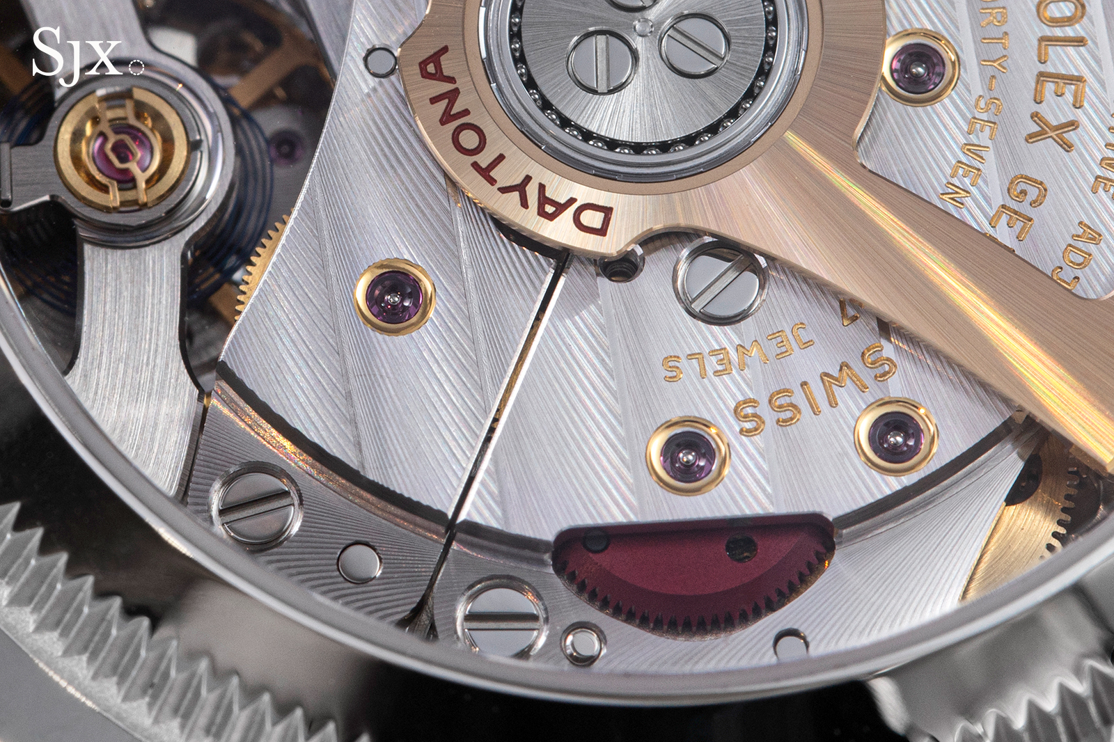
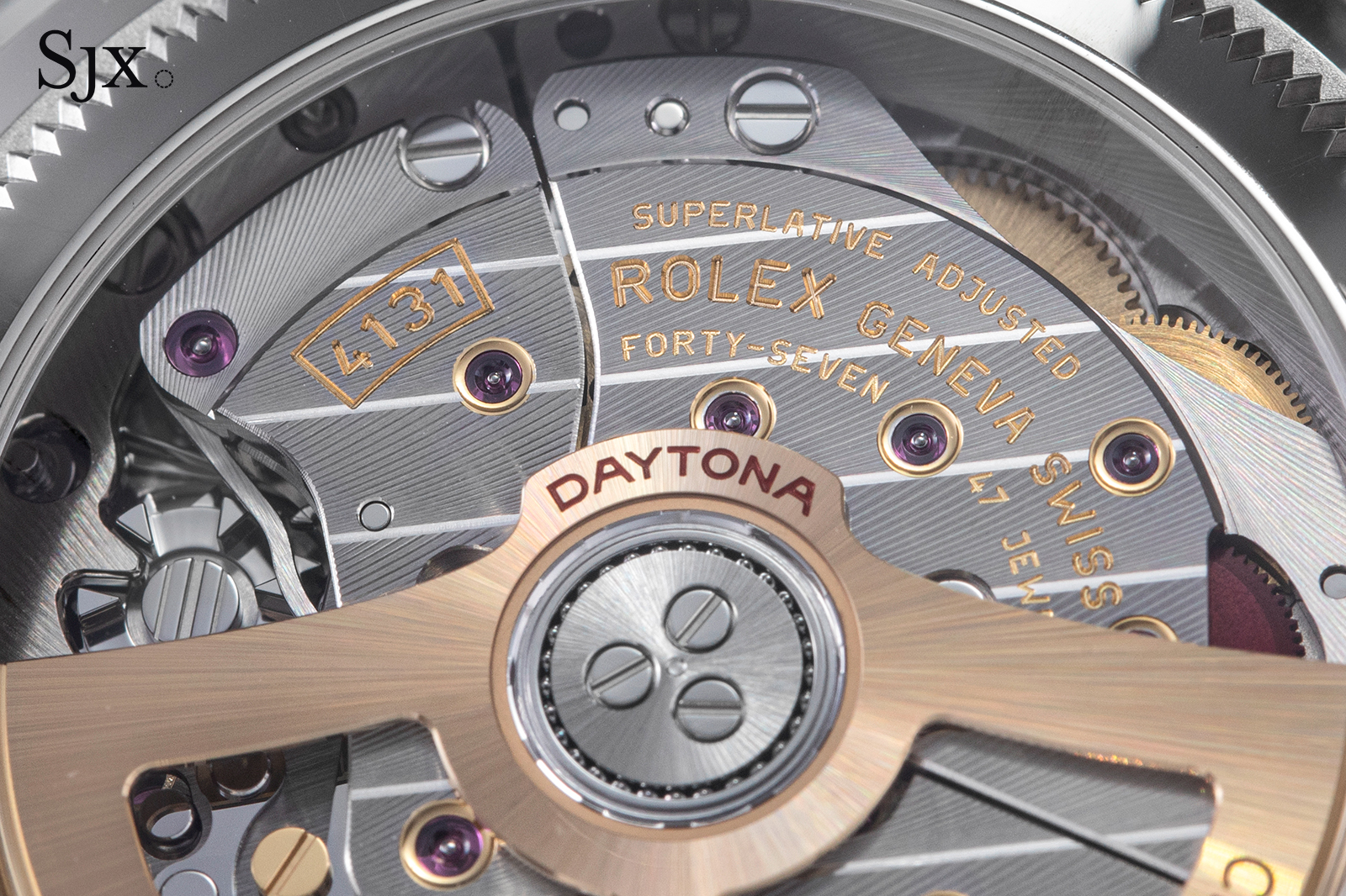
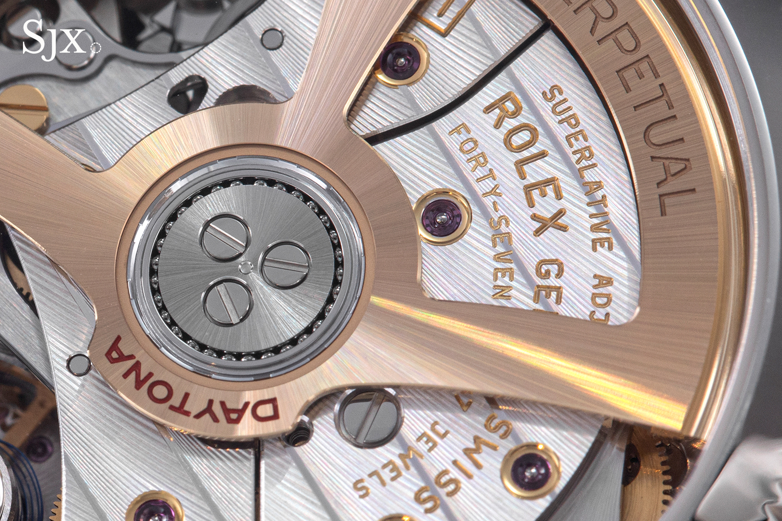
The latest Daytona movements reveal a degree of decorative finishing unseen in past generations of Rolex movements
An already quirky base
For over two decades, the Rolex cal. 4130 stood as the benchmark for industrial chronograph movements. Launched in 2000, the cal. 4130 was the first in-house chronograph movement developed by Rolex. The movement was lauded for its compact architecture, low component count, and ease of service – attributes that marked a shift from the complex Zenith El Primero-based cal. 4030 it replaced. Its success influenced competitors, with echoes of its design seen in movements like the Breitling B01 and Omega cal. 9900 series.
In 2023, the cal. 4130 was succeeded by the cal. 4131, a movement that looked similar but incorporated incremental upgrades, including the Chronergy escapement and improved decoration. While not a ground-up redesign, the cal. 4131 benefited from more than 20 years of service feedback; many components previously introduced during service, such as LIGA wheels with sprung teeth and hairspring guards, were likely made standard in the new movement.
A sibling of the cal. 4131 is the elusive cal. 4132 that debuted in the Daytona “Le Mans”. Introduced to mark the centenary of the 24 Hours of Le Mans, the ref. 126529 LN features a full 24-hour chronograph totaliser – double the industry norm of 12 hours and also that of prior Daytona models.
Beneath its 18k gold winding rotor and industrial decoration lies a small mechanical assembly that enables the 24-hour function, an elegant solution to a tricky problem. That Rolex managed to implement this without altering the underlying cal. 413x architecture speaks to the ingenuity of its design team. But achieving this required rethinking a fundamental constraint of the original cal. 4130 layout.
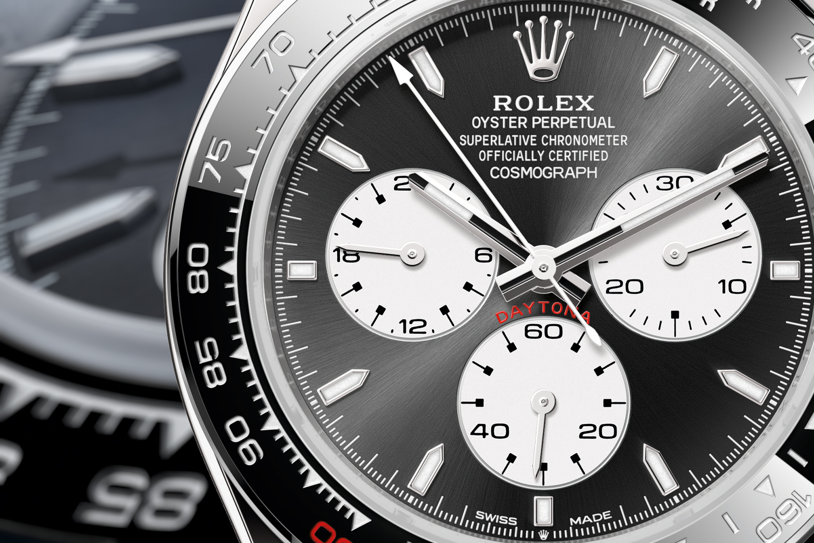
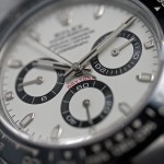
The Daytona Le Mans with its “Paul Newman” inspired dial design
Solving one problem created another
One defining feature of the cal. 413x family is its quasi-modular construction: the automatic winding module can be detached almost as a unit, granting easy access to the chronograph works.
The chronograph works are tightly packed, with the control elements (column wheel, levers, and reset hammers), vertical clutch and chronograph train all closely laid out. This allows the watchmaker to easily service the chronograph works without dismantling the entire movement. This approach sounds simple, but it marked a significant shift in chronograph design.
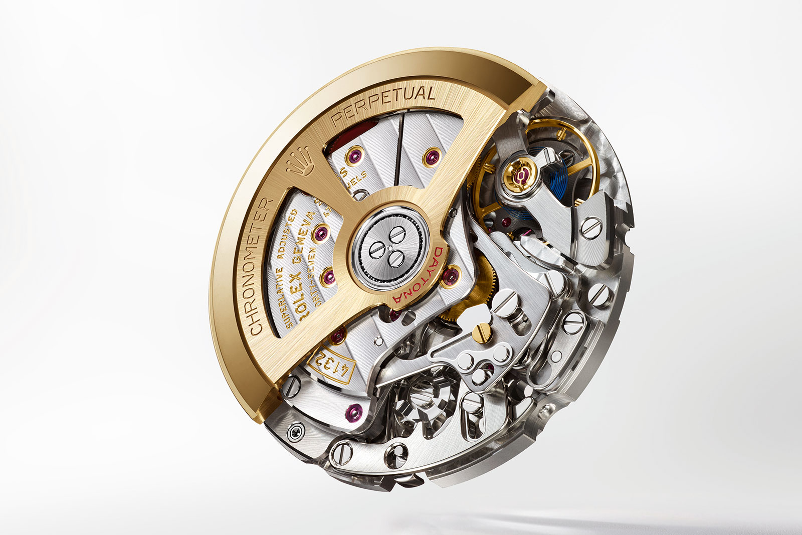
The Rolex cal. 4132 in the Le Mans. Image – Rolex
In classic chronograph movements, from historical Lemania hand-wound calibres to the industrialised Valjoux cal. 7750, the chronograph hour register is directly driven by the barrel with a crude system of friction bushings and brakes. This system is usually found on the dial side of the movement, and it usually takes a full movement strip-down for the watchmaker to access it.
With a barrel-driven totaliser, doubling the hour register to 24 hours was a straightforward affair of changing the gearing ratio. But because the cal. 413x took a more concise approach to the chronograph construction, the traditional method of doubling the 12-hour totaliser on the dial side was no longer viable; it would require a clever new solution.
Understanding the problem
To understand how Rolex solved this conundrum, it’s helpful to understand the arrangement of the cal. 4130’s chronograph train. Figure I, below, shows the outline of the entire chronograph train, from seconds to minute and hour counters, complete with the vertical clutch. The diagram is in the original patent granted in 1999, and the three different gear flows are colour-coded.
The lowermost yellow circle (dotted line) is part of the vertical clutch pack and engages with the central chronograph seconds mobile. This is the top-most level of the central stack of wheels.
The blue train of gears leads to the 30-minute counter. The central gear is driven in steps by a finger (not shown) of the vertical clutch and has 30 teeth. The transmission ratio from this central wheel to the actual minute counter is 1:1, which accounts for the Daytona’s 30-minute totaliser.
Bolted under the large central wheel is another gear much smaller in diameter, outlined in a red dashed line. This gear engages a compound gear train (all highlighted in red) which drives the 12-hour counter.
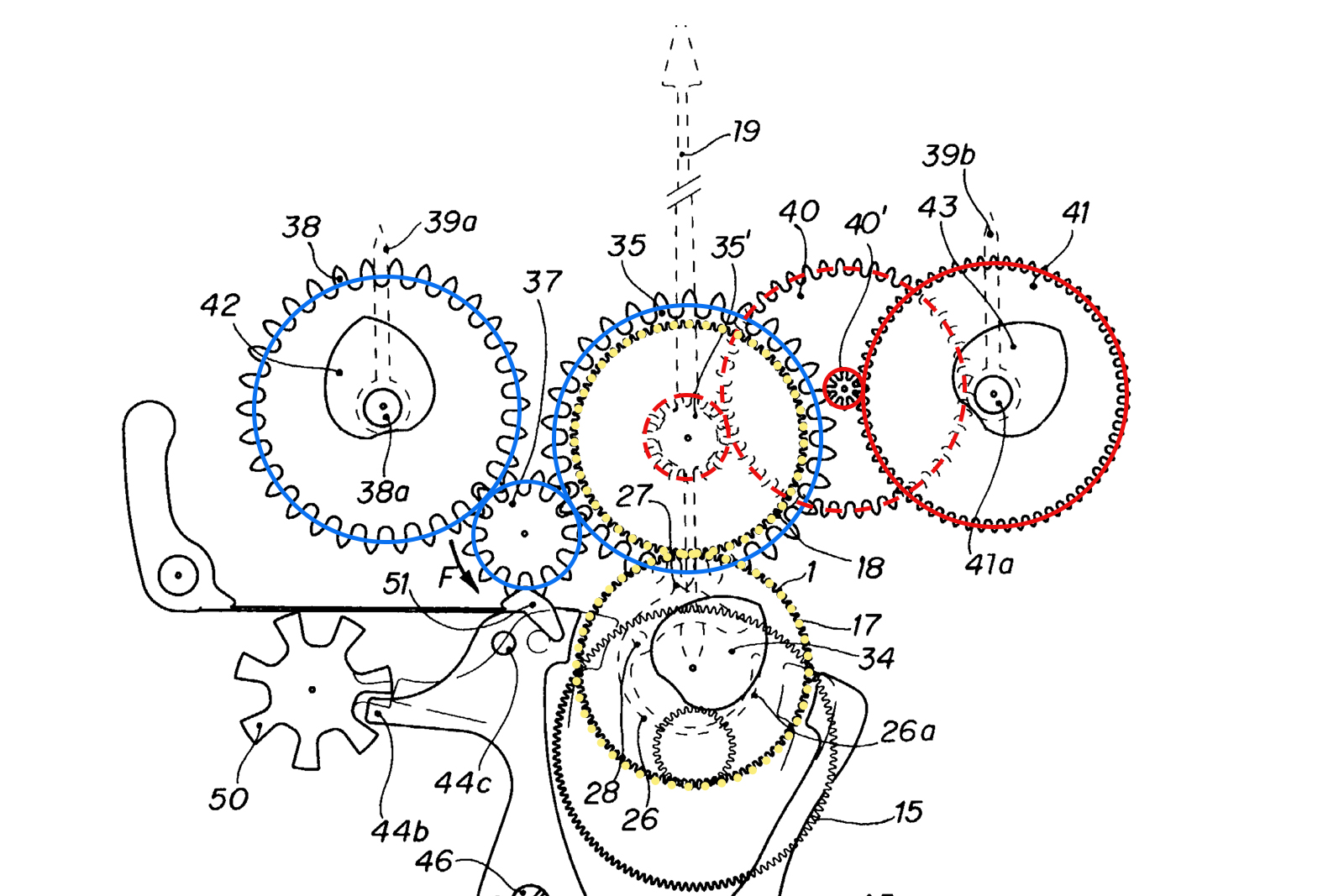
Figure I. The general outline of the cal. 4130 chronograph train.
The gear reduction that makes the standard 12-hour counter possible is illustrated in more detail in Figure II, below.
As mentioned, the clutch mobile turns once every minute, engaging the mobile 20 (yellow and green) at each passing. Having 30 teeth, wheel 20a (yellow) thus makes a full turn each half an hour. Its motion is transmitted via pinion 50 to the minute counter 60 and the final ratio is 1:1, which gives the Daytona its 30-minute chronograph counter. Also note the indexing finger 71, which keeps pinion 50 under tension and serves as the main indexing element for the whole gear train.
Co-axial with wheel 20a (yet not fully visible) is another gear, outlined in green. It has 30 teeth as well, but a much smaller module compared to 20a. In gear terminology, the module is the ratio of gear pitch diameter over number of teeth. In order for two meshing gears to be compatible, their module needs to be the same.
The entire mobile 20 is usually bolted onto the movement bridge, around a jewelled bearing. The central jewel serves as a bushing for the chronograph seconds hand and the assembly is very rarely taken apart during routine service and cleaning.
The green smaller wheel makes one turn every half an hour as well (since it is part of mobile 20) and meshes with the large purple wheel 31a’. Gear 31a’ sits co-axial with a small pinion 34b’, left here in white. The small pinion finally engages with wheel 40a (red) which serves as the 12-hour counter.
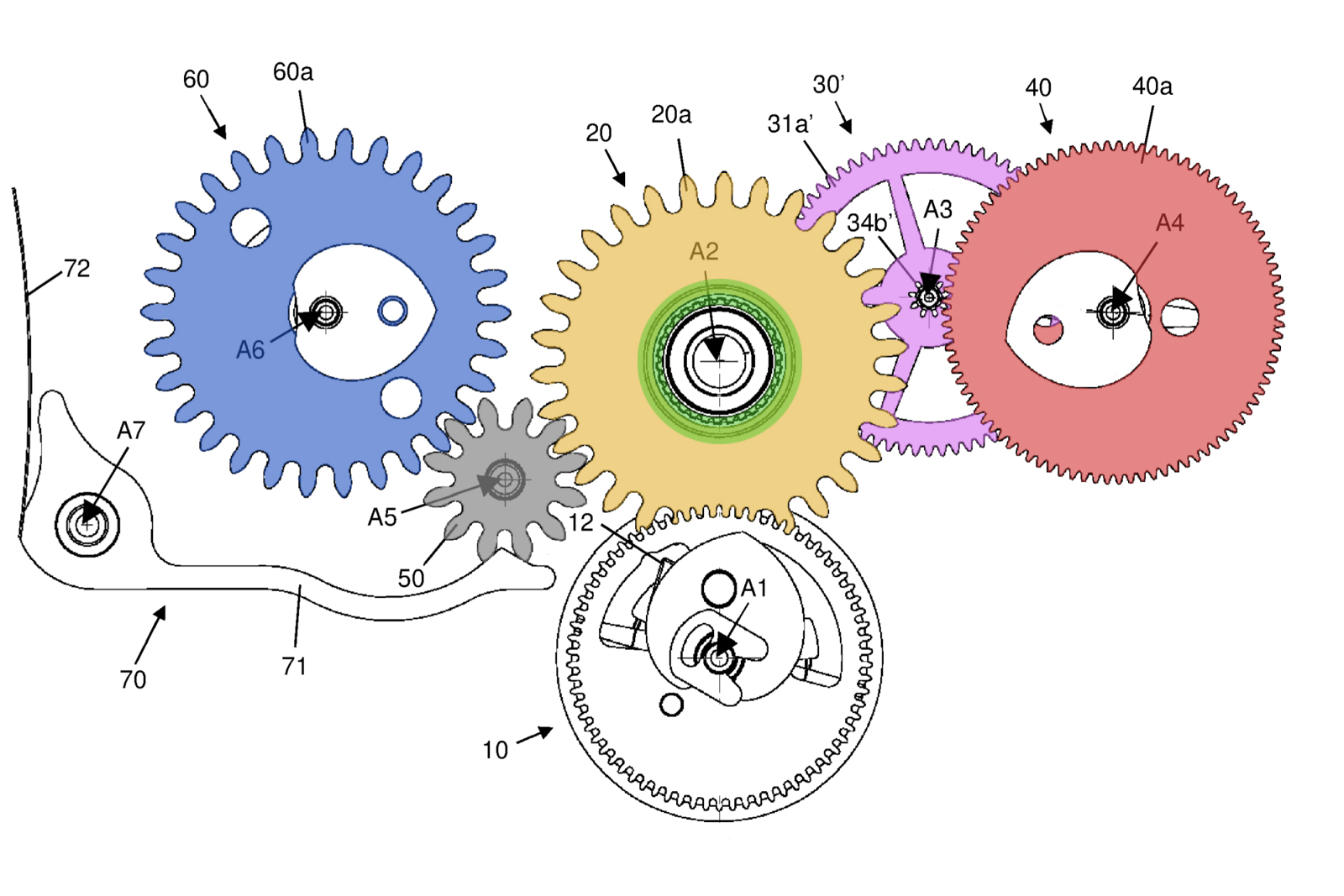
Figure II. The basic 4131 chronograph train in greater detail.
So how does this all work? The needed transmission ratio for transforming the rate of two turns per hour into one turn every 12 hours is a rather sharp 1:24. The green gear has 30 teeth and the purple 31a’ has 72 teeth. This gives a first ratio of 30:72, or 5:12. Pinion 34b’ has 9 leaves and gear 40a has an impressive 90 teeth, making for a second ratio of 9:90, or 1:10.
Multiplying the ratios together eventually gives us a final 5:120 which simplifies to 1:24; exactly the ratio initially required. This sort of reduction gearing is complicated to put in place, since the practical and different modules need to be taken into account during construction, since the gears can’t interfere with one another and need to fit in a tight space.
Turning 12 into 24 with a differential
Following the previous reasoning, the cal. 4132 in the Le Mans Daytona needs to exploit an even sharper 1:48 ratio for its 24-hour counter. Because of tight space constraints, namely the requirement for the 24-hour counter to fit into the same space as the 12-hour reduction train, Rolex needed to find an ingenious solution when building the cal. 4132 chronograph train. This is where a clever differential gear set enters the picture.
A valuable mechanical device, differential gears are used in many fields of engineering, such as in automotive transmissions. In watchmaking, differential gear sets are most commonly used for power reserve indicators or timepieces with two balance wheels like the Dufour Duality.
The Rolex cal. 4132 uses a differential compound gearset to half-down the ratio of 1:24 to 1:48, while managing to fit in the same available space. The device is detailed in patent EP3944026A1 filed as early as 2020.
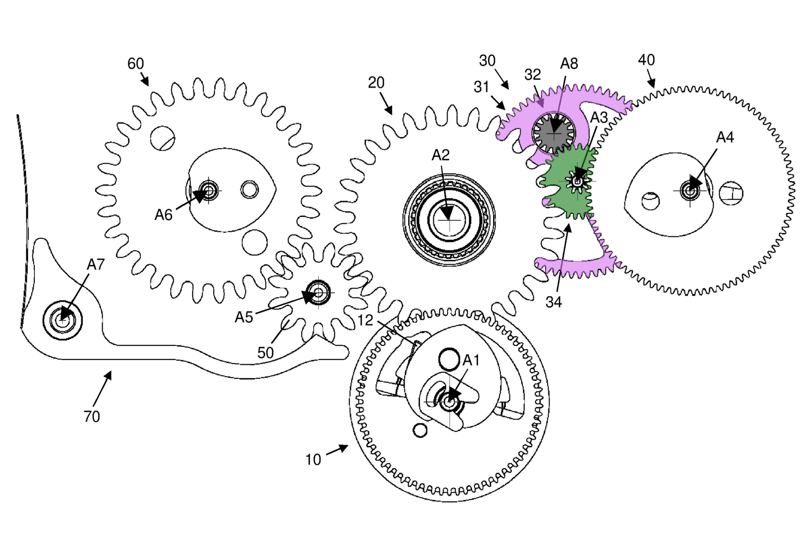
Figure III.
Figure III (above) shows the updated chronograph train suggested for the cal. 4132 architecture. An important aspect highlighted in the patent is the ability of the new system to fit the standard cal. 413x base, without any modification to the supporting bridges.
As a result, the familiar cal. 413x architecture is apparent in Figure III. The central mobile 20 was preserved, along with the minutes’ counter train. Wheel 40 was kept as well, serving as the hour counter. The big change concerns mobile 30, which is now more sophisticated compared to the wheel-pinion assembly found in the basic cal. 413x.
The purple wheel 31 acts as a carrier for the planetary gearset. The grey gear 32 serves as a satellite and the green 34 gear is the sun gear. There is also a fixed gear under the large carrier 31 (not shown).
An important takeaway is that apart from the differential setup, the gears retain their original tooth counts. That is to say gear 31 still has 72 teeth, the pinion has 9 leafs and gear 40 retains its 90 teeth. The compound differential is thus required to have a 1:2 input-to-output transmission ratio.
Figure IV (below) shows the compound differential assembly 30 in greater detail. Top to bottom, we have the following components: mobile 34 (which joins pinion 34b with the green gear 34a and serves as the output shaft), carrier 31, satellite gears 32a and 32b which share the same shaft and lastly the fixed gear 33.
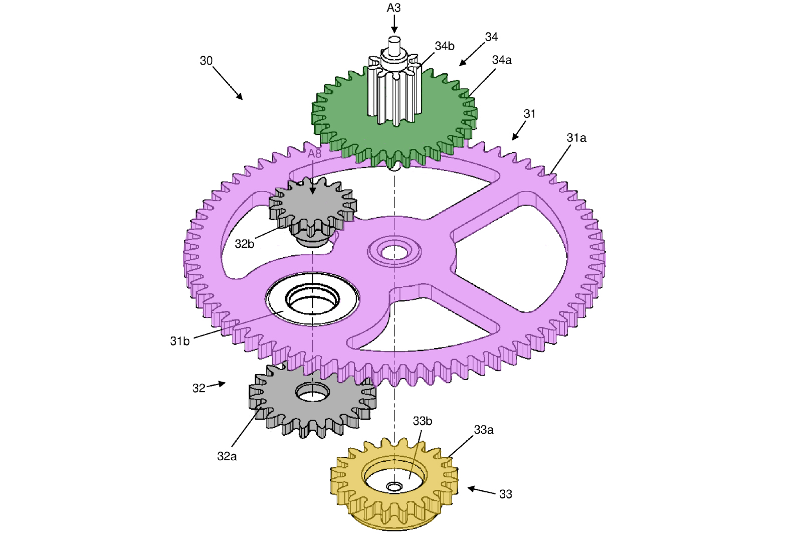
Figure IV. Exploded view of the differential assembly.
The source of motion here is provided by the carrier 31, which is entertained in rotation by the central mobile. As gear 33 is practically bolted into the movement bridge, it remains stationary. As carrier 31 rotates, it rotates gear 32a around the fixed 33 component, making it turn. Gear 32b thus makes gear 34 turn — linking the input motion (31) to the output (via 34b).
The patent details the construction, yet it doesn’t shed any light on the actual transmission ratios. We will try here to derive the definitive transmission ratio, from input to output and explain how it works.
In a past story on the Ulysse Nardin Freak we have used the Willis equation for planetary gears in order to describe the motion of a simple epicyclic gearset. Here we need to derive our own suitable relation, considering the relative and absolute angular motions of the system.
Figure V details the notations of the different angular velocities and tooth counts we’ll use in our reasoning. The term “absolute” was used in order to reference the velocity of a given component relative to the inertial “ground” reference frame. Since the device involves satellite gears set into a rotating carrier, we will start our computation with relative velocities. “Relative” here means “in regards to the carrier 31”.
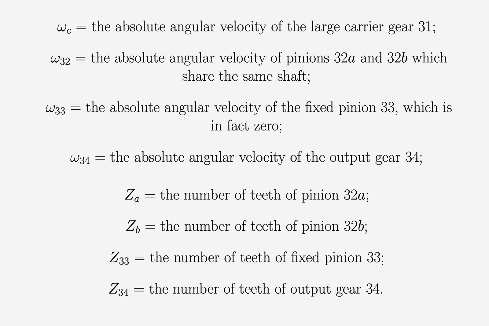
Figure V.
For the mathematically inclined, the complete reasoning is found below, in Figure VI. The first line describes the relation of the relative angular velocities between gear 32a and 33. The two relative velocities are obtained by subtracting ωc from both ω32 and ω33. Multiplied by the gears’ respective tooth counts, they add up to zero since the angular velocities of meshing gears are opposite in sign.
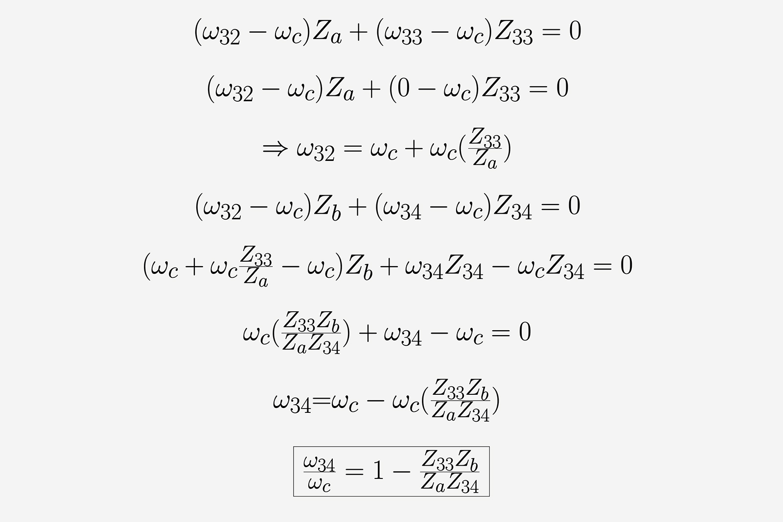
Figure VI. The mathematical reasoning.
By some algebraic manipulation we obtain the expression of ω32 in terms of ωc, shown in the third row. In the fourth row we then express the relative motions of gears 32b and the output 34, using the same reasoning as before.
After some more algebraic manipulation, we finally obtain the exact relation between the input speed of the carrier ωc and the output speed ω34. The desired ω34:ωc ratio is in fact a positive 1:2, which is obtained by subtracting 1/2 from 1. And thus we have the necessary tooth count condition for the gearset’s components.
We can put our theoretical result to test by a trivial tooth count based off Figure IV. The first ratio, Z33:Za, is simply 1:1. Moving up a level, we see that Zb is 15 and Z34 is 30, yielding our desired ratio of exactly 1:2.
Our past theoretical reasoning seems to be validated by this elementary observation. An almost identical construction is employed by Rolex in cal. 4132, save for a reduced 9 teeth for 32b and conceivably 18 teeth for the output member 34. The change was done for manufacturing purposes, since fewer teeth are bigger for a given gear pitch diameter and thus don’t require the same tight tolerances.
The assembly for the 24-hour counter. Image – Rolex
Rolex argues in its patent that this assembly can be implemented in the standard cal. 4131 without any alterations done to the bridge settings. This means any modern Daytona from the past 25 years can easily be updated to have a 24-hour counter.
In reality, it’s unlikely we’ll see system used in regular-production models, but it is nice that Rolex put all this effort into designing such an elegant system that is compatible with existing movements, leaving the door open for future possibilities.
Concluding thoughts
This analysis reveals the kind of thoughtful long-term thinking that many enthusiasts associate with Rolex. It shows that while the brand can appear overly conservative at times, there’s a lot going on behind the opaque glass facade.
Looking to the future, it’s worth noting that similar differential gear sets are usually used in forming power reserve indications, so we may see more differentials from Rolex. A power reserve indicator would be especially at home in the dressier 1908 collection.
Back to top.