The Ulysse Nardin Freak – The Saga of a Scientific Timepiece Part I
An in-depth history of its technical development.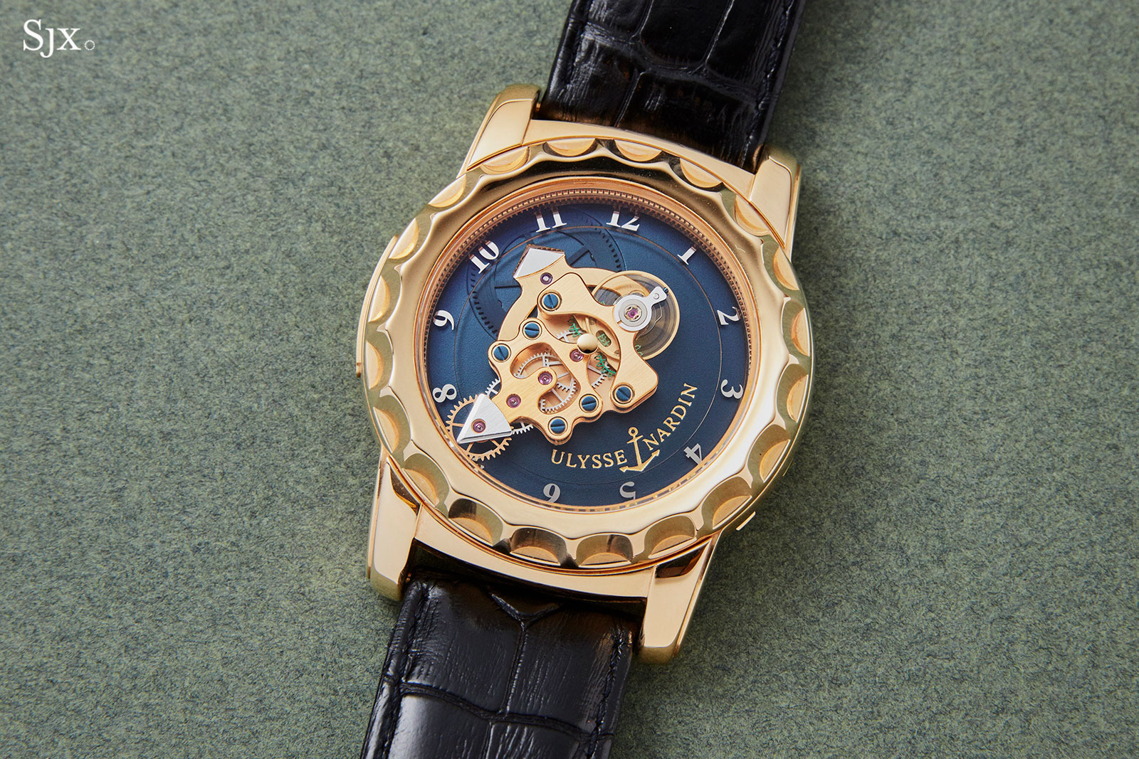
Novel ways of telling the time or exhibiting the movement have long been the focus of the avant-garde horologists. Independent watchmakers like Ressence or Urwerk have built their brands on doing away with conventional hands. Such idiosyncratic approaches to watchmaking challenge the traditions of horology, making for a more interesting horological landscape.
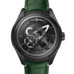
Even before Urwerk introduced the pioneering three-dimensional cubic hour display in 2005, there was the Ulysse Nardin Freak. Launched in 2001, the Freak literally changed the face of watchmaking by transposing the movement into the dial. Two decades after its launch, the Freak is still regarded as a landmark for its audacity, from both aesthetic and technical perspective.
[This story covers the origins of the Freak, from its conception to realisation, as well as its distinguishing characteristics, namely the inventive movement construction and unique escapement. Part II deals with the evolution of the unique, high-performance escapement, while Part III details the history of silicium, the proprietary Ulysse Nardin silicium hairspring, and the patented Grinder rotor.]
The origins
The beginning of the Freak lay in 1997, when Carole Forestier-Kasapi, then a young and talented movement designer who only recently graduated from technical college, won the Prix de la Fondation Abraham-Louis Breguet, a contest conceived to mark A.-L. Breguet’s 250th birthday that sought to recognise watchmaking ingenuity.
Now the head of movement development at TAG Heuer, Ms Forestier-Kasapi claimed the prize with a concept that featured a revolving movement containing a mainspring enclosed in a donut-like barrel almost as wide as the case. Seated within the barrel was the gear train and regulator. The concept watch had no crown, with the setting and winding accomplished by turning the bezel.
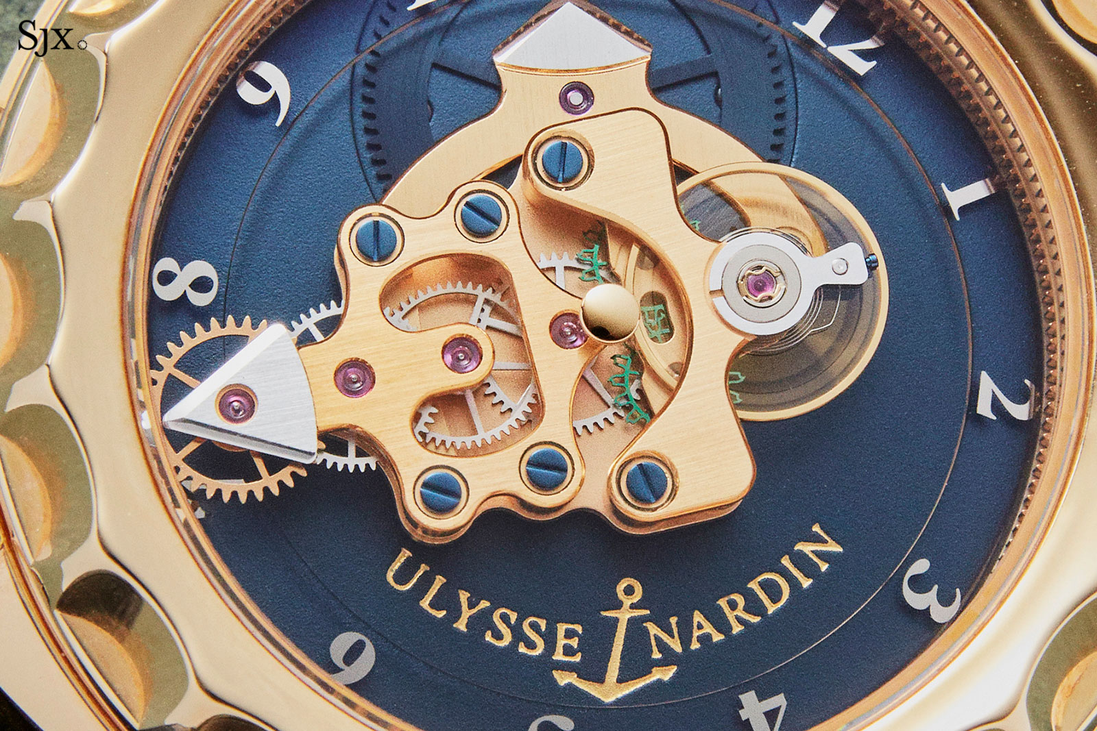
The original drawing for the Freak Concept by Carol Forestier-Kasapi. Image – Ulysse Nardin
After winning the prize, Ms Forestier-Kasapi then joined Ulysse Nardin, a once-illustrious firm famous for its marine chronometers that was laid low by the Quartz Crisis. Led by its then owner, the visionary Rolf Schnyder, the firm embarked on a comeback starting in the late 1980s, propelled in large by its brilliant technical director, Dr Ludwig Oechslin.
That period saw Ulysse Nardin launch the Trilogy of Time series of astronomical complications – which gained a spot in the Guinness Book of Records in 1989 as the most complicated watches in production – and the clever Perpetual Ludwig, a perpetual calendar that could be set backwards and forwards.
In keeping with the brand’s innovation-driven approach to products at the time, Schnyder showed great interest in transforming Ms Forestier-Kasapi’s prize-winning concept into a serially-produced watch. Unsurprisingly, commercialising the radical concept quickly ran into difficulty.
The inventive donut-like mainspring barrel was not practical as it imposed limits on the size of the mainspring, which meant it could only power the energy-hungry movement for only about 15 hours on a full wind. This prompted a rethinking of the idea right down to its fundamentals.
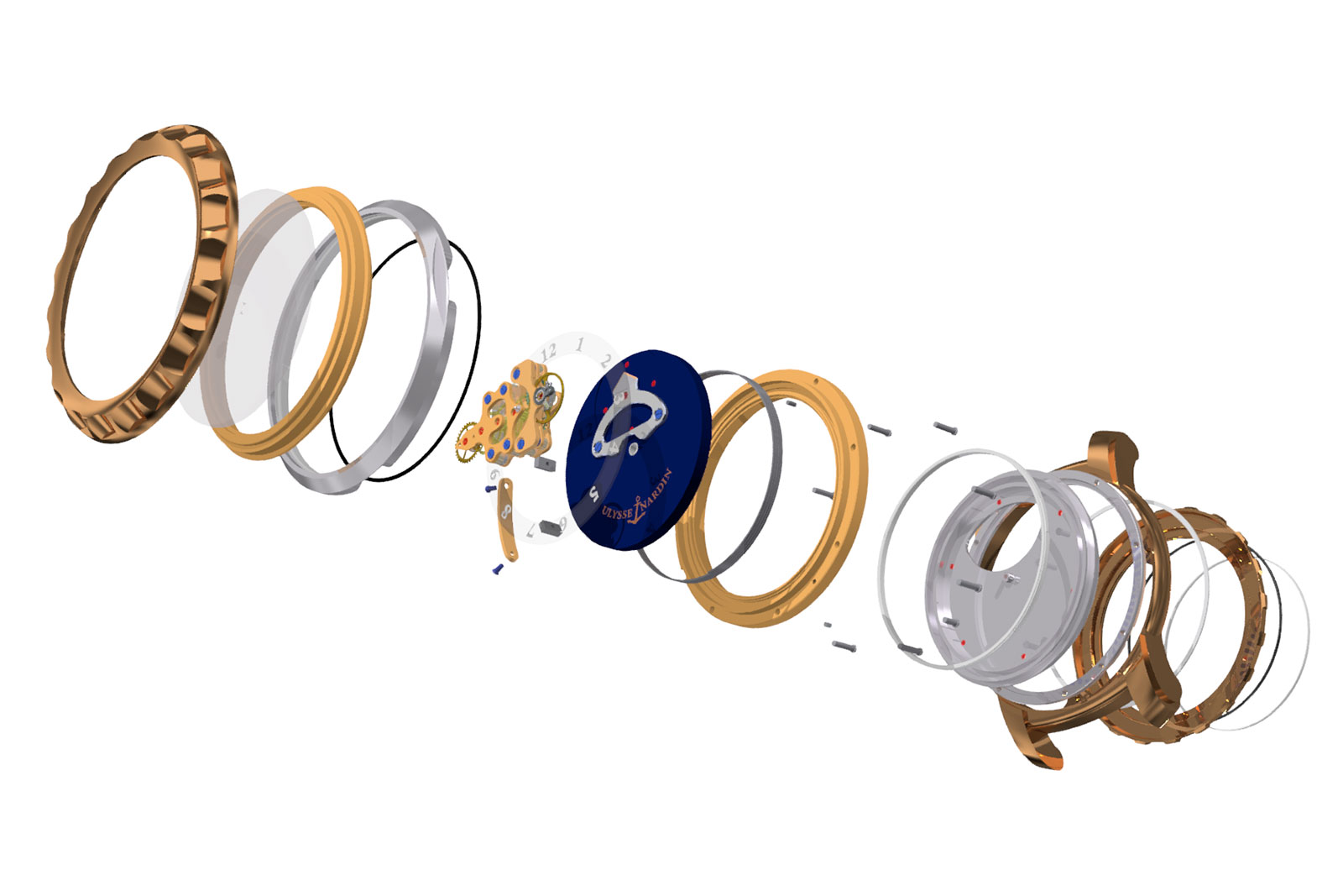
Exploded view of the 2001 Freak. Image – Ulysse Nardin
Tasked with making the revolving-movement watch feasible, Dr. Oechslin drastically altered the approach to create a movement that remains unique to this day. With an eclectic education – including degrees in archaeology, ancient history, theoretical physics, and philosophy – and hands-on experience with horological restoration, Dr Oechslin is a rarity in watchmaking – a polymath able to tackle demanding complications in radical ways.
Despite its utterly unorthodox construction, the Freak is illustrative of Dr Oechslin’s philosophy, one that often employs inventive use of gearings and applied mathematics, an approach closer to a mathematician’s workings rather than a watchmaker’s engineering.
The basic principles
Ms Forestier-Kasapi’s original construction was unsuited to large scale production. The design was energy-intensive in operation but had little space for a mainspring large enough to power the movement for a reasonable length of time. In her design, the mainspring had to fit inside within the donut-shaped hub between the movement and case.
After taking over the development of the watch, Dr Oechslin rethought the concept, most famously installing the huge mainspring under the movement. The barrel was not merely relocated, but was fundamentally reworked to transform it into an active component of the time display.
The Freak’s trademark feature was always the way it tells the time, with the going train doubling as an oversized minute hand, while the barrel cover functions as the hour hand. Intriguing and striking at the same time, the movement-as-hands construction might seem much more complex than a conventional movement. Surprisingly, this is not the case – and now we’ll see why.
The hour hand
The first prototype created by Dr Oechslin already had all of the elements that defined the subsequent production model. A large coiled mainspring is visible through the cut-outs in the base plate, which is actually the barrel cover.
Despite its unusual size and placement, the barrel is almost identical to a regular barrel in form and function, being essentially drum containing a long spring coiled around a central arbour. The outer end of the mainspring connects to the barrel’s walls while the innermost end connects to the arbour.
The first Freak prototype built by Ludwig Oechslin. Image – Ulysse Nardin
Functionally, the barrel of the Freak also operates on the same principles as a conventional barrel. As the arbour is turned when winding the watch, the coils of the spring tighten, storing potential elastic energy. Once fully coiled, the spring begins to rotate the barrel in the opposite direction as its outer coil pulls the barrel along as the spring unwinds.
Conventional barrels feature a toothed rim on the outside of the barrel that engages with the second wheel of the going train (the barrel serves as the first wheel of the gear train).
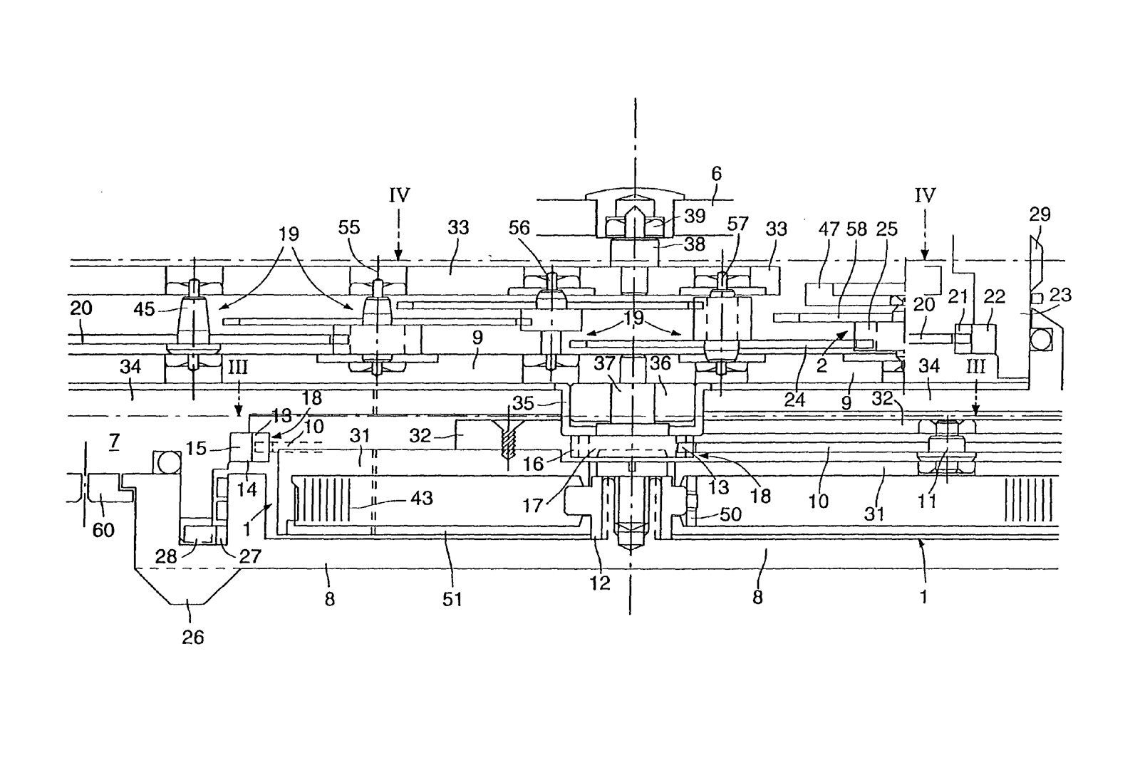
Fig. 1
The barrel construction of the Freak relies on complex gearing to achieve a simple, useful goal: a rotation ratio of 12 between the hour and minute hands. In other words, the minute hand makes 12 revolutions around the dial in the same time the hour hand completes one revolution. Here, we explain how that is accomplished.
The Freak’s large barrel sits very low in the case and doesn’t feature any teeth on its rim. As seen in the sectional diagram in fig. 1, the arbour is rigidly joined with a generous click wheel, which works with a pair of clicks to limit the arbor’s rotation to one direction only. The click wheel is directly linked to the timepiece’s case back.
By construction, the case back is free to pivot on ball bearings, in for the wearer to wind the watch by rotating the back in the proper direction. The mainspring is set in such way that it drives the barrel in a clockwise direction when unwinding, when seen from the dial. It is important to note that the barrel is free to fully turn inside the case.
The mainspring is of unusually long length and substantial thickness, making it a powerful motor for the movement. Due to its enormous size, manually winding the mainspring with a conventionally-sized crown would be tedious and bordering on the impossible. Winding the spring directly through the large diameter case back is much more convenient, with increased grip and leverage both work in favour of the user.
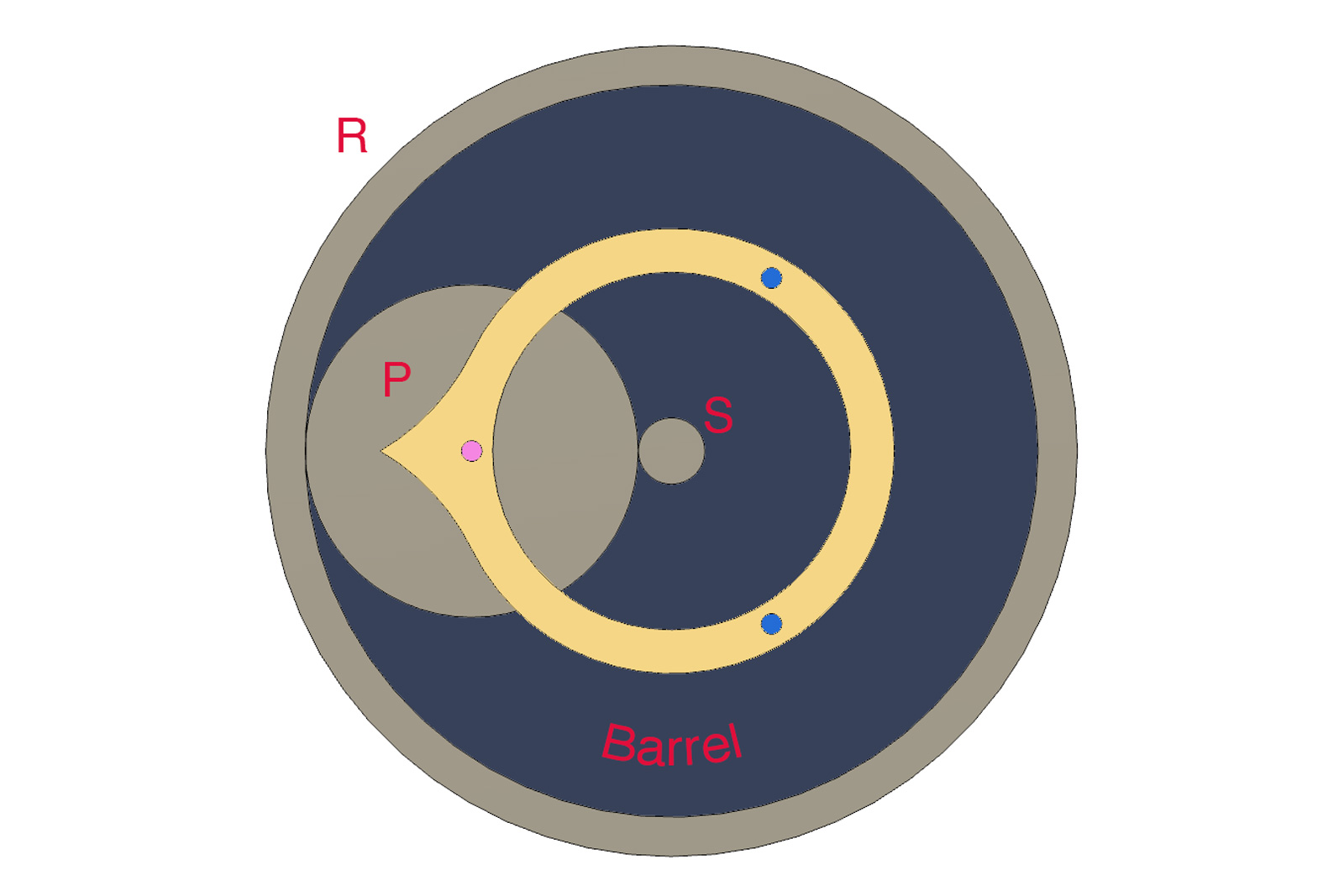
Fig. 2
At its core, the Freak is a realisation of planetary gearing. Planetary, or epicyclic, gears have many uses in very diverse fields of mechanical engineering due to some useful proprieties. For example, car transmissions and gearboxes usually implement a number of planetary gears.
In watchmaking, planetary gears are sometimes used for power reserve indicators. In the Freak’s case, the planetary gear takes centre stage. Every basic planetary gear set comprises of a ring gear (marked R in fig. 2), a planet gear (marked P), a carrier (the blue barrel cover in this instance) that carries the planet gear, and lastly a sun gear (marked S).
Although they share the same axis, wheel S turns independently from the carrier (barrel), so the latter’s movement doesn’t directly influence the former. Gear P securely pivots between the barrel and the bejewelled gold bridge/ hour indicator. It engages with both S and the internal toothing of the ring R.
While P and S are free to move, ring R is rigidly joined to the case, remaining stationary. As stated, under the strain of the mainspring, the barrel tends to spin in a clockwise manner.
Once the barrel is wound and starts moving. Wheel P, carried by the barrel and its affixed bridge, turns around its axis dragged against the stationary internal toothing of R. In turn, this engages S in rotation around its own axis, but at a different angular velocity compared to the barrel.
It may be difficult at first to determine the transmission ratios from one gear to another, since this is not a conventional gear train. But since the arrangement forms a classic planetary set, the Willis equation for planetary gears can be applied.
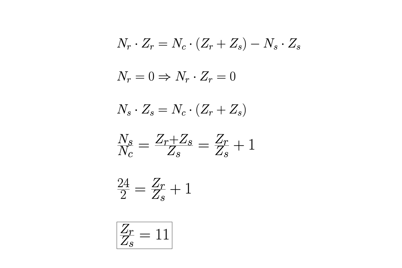
Fig. 3
The fundamental equation of planetary gears, also known as the Willis equation, is a very useful mathematical expression that describes the motion of individual components in a planetary gear.
Fig. 3 shows firstly the general form of the equation, with the following conventions: Nr is the number of revolutions per day of the ring gear, Nc is that of the carrier and finally Ns is that of the sun gear; Zr and Zs are the numbers of teeth for the ring and sun gears, respectively.
In the case of the Freak, the ring R is fixed, thus stationary, so its number of daily revolutions Nr must be zero. The number of daily revolutions of the carrier Nc is 2, because it doubles as an hours indicator that goes around the dial twice a day. The sun gear S carries the minute hand/secondary gear train, which means it makes 24 revolutions around the dial each day, one revolution per hour, so Ns is 24.
By subtracting the figure from our equation and after some subsequent simplifications, we are left with the useful ratio between the number of teeth of the ring and sun gears. Common to most Freak models, 16 is the number of teeth for S, which implies 176 teeth for the ring R, according to the ratio found above. In this manner, the barrel turns once for every 12 revolutions of the sun gear, exactly the traditional ratio between the hour and minute hands.

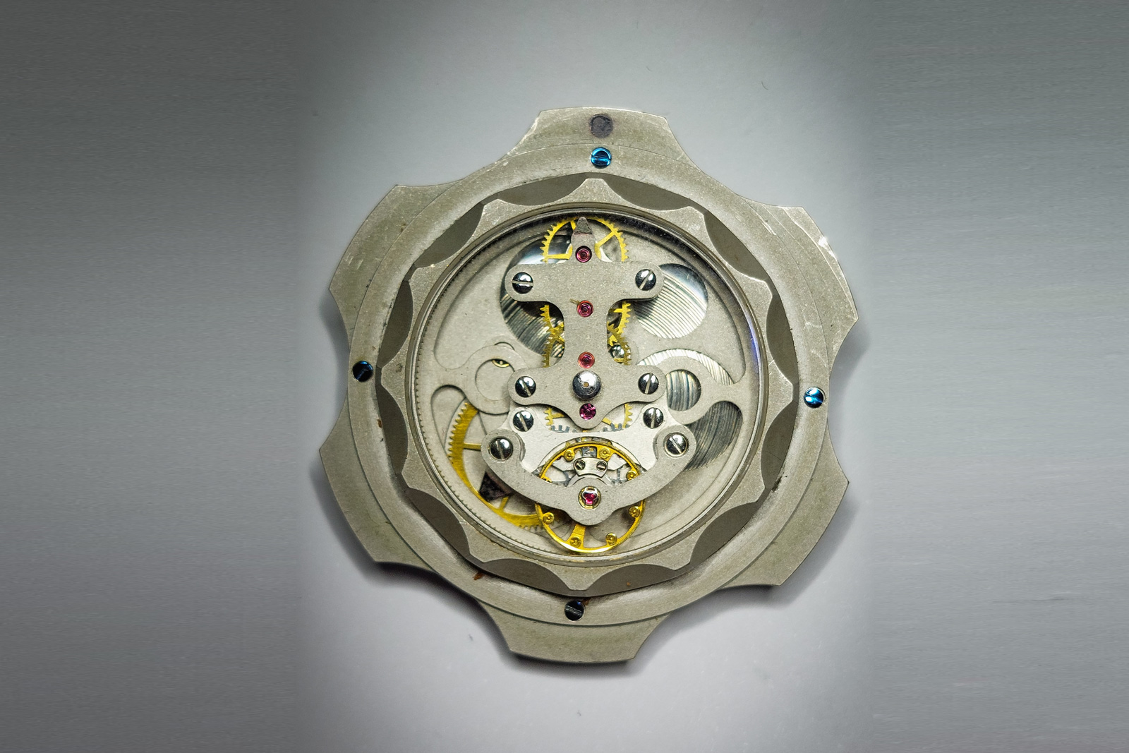
The case back of the original Freak revealing the barrel within and the coils of the mainspring
The minute hand
The velocity ratio between the hour indicator and centre pinion has been established above, leaving only the need to regulate the discharge of power from the barrel as the mainspring unwinds. This is done in a fairly conventional way, using a sprung regulator and a set of going gears, very much like an ordinary movement.
The centre pinion S is larger than usual to carry the minute hand platform. The platform, in turn carries a going train, which is laid out in a similar manner as classical constructions.
The method of power transfer, however, is uncommon, as the barrel doesn’t directly engage with the going train. Instead, the going train engages at one end with an interior ring gear. This interior gear is only virtually stationary, unlike the R component in the planetary assembly. It is connected to the watch case’s turning bezel, which allows the wearer to indirectly act on the going train. But unless it is engaged from the bezel, the ring gear remains stationary.
As the base pinion turns, it carries the minute platform with it. Dragged along by the interior gear, the going train springs to life, eventually engaging the escapement and balance. In the classical fashion, when the escapement is locked, the entire system, platform to mainspring, stops.
The balance frequency and gearing ratios are computed to conveniently allow the platform to fully turn once every 60 minutes, enabling it to act as the minute hand. The component gears are highlighted in fig 4. They bear a striking resemblance to classical going trains, which sometimes leads to the conclusion the entire calibre is housed in the rotating platform. This is only in partly true, as we’ve seen that the movement architecture goes deeper than that.
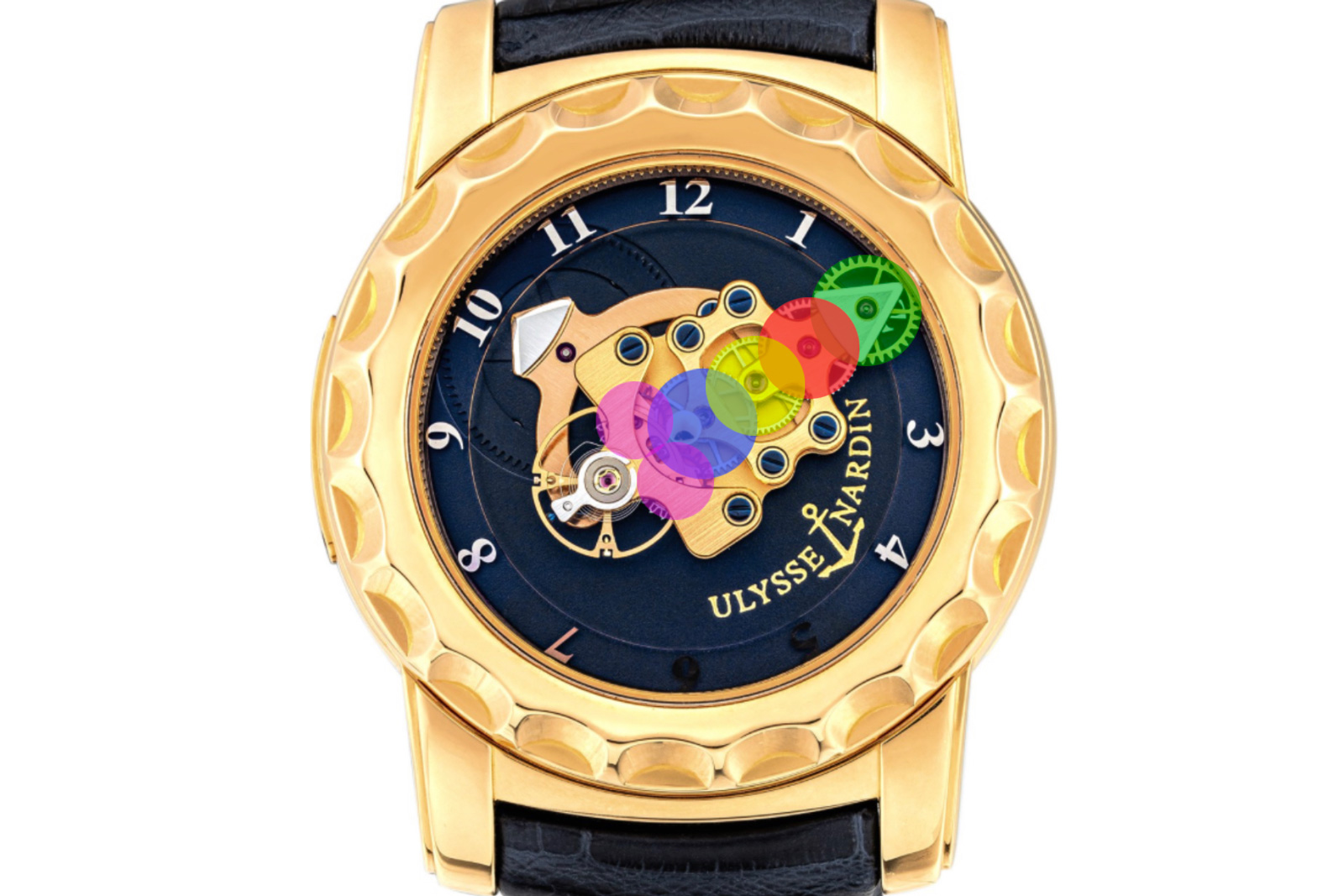
Fig. 4
The quirky time setting of the Freak is famously done by turning the watch’s front bezel. In the original model, the bezel had a wave-patterned edge resembling a bottle cap, a nod to Ulysse Nardin’s maritime heritage and a concession to utility.
As discussed above, the internal ring gear engaging the minute platform is directly linked to the bezel. In theory, this would lead to some problems. Turning the bezel should theoretically disrupt the power flow from the mainspring to the escapement. And setting the time implies moving the minutes and hours hands against the gears.
Since the hour indicator is basically the barrel, setting the time and disrupting the barrel’s rotating motion would mean acting directly on the mainspring. In that case, it stands to reason that setting the Freak clockwise should unwind the barrel, while setting it counter clockwise would wind it, imposing excess stress the mechanism.
The solution to that is the implementation of a slipping bridle on the mainspring. Commonly found it automatic movements, the bridle allows the mainspring to safely “slip” along the interior barrel walls when fully coiled, while still exerting torque. This is done to prevent breakage of a fully wound mainspring even as the automatic mechanism continues to wind.
In the Freak’s case, the implementation of the slipping bridle means that the barrel is allowed to turn freely without upsetting the mainspring inside, with a minimal loss of exerted torque.
Even with that in place, the Freak balance severely drops in amplitude during time adjustment, as the normal torque flow is disrupted and the escapement loses power, but the effect on timekeeping is minimal since the time setting doesn’t take long and the full power flow instantly resumes afterwards.
The original 2001 Freak featured an almost free-turning bezel, kept stationary only by the friction of the sealing gaskets inside the case. The wearer was free to adjust the time at any time, without the need to engage a particular setting mode. As a result, the bezel was prone to move almost on its own, as the mainspring tension was travelling directly into the bezel’s internal ring, making it susceptible to rotate at the slightest bump or brush against something.
This was rectified in subsequent versions of the Freak, which all featured a hinged, locking tab at the base of the bezel. When the tab is engaged and sits flat on the case, it puts pressure on the bezel, forming a simple locking mechanism. Lifting the tab unlocks the bezel for time setting, a solution that was surprisingly simple and elegant, yet practical.
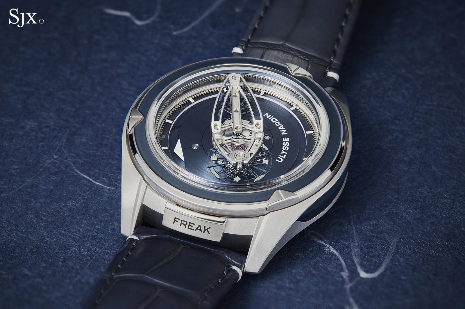
The locking tab also serves a decorative function since it can be engraved, as shown here on the Freak Vision
Tourbillon or karrusel?
Probably the quintessential invention of A.-L. Breguet, the tourbillon was invented to compensate for poising defects and subsequent positional rate errors. Breguet’s invention continually rotated the oscillating organ around its own axis, effectively cancelling the poising errors.
Impressed by the tourbillon, Bahne Bonniksen, a German horologist and inventor who settled in England, set out to adapt and improve on Breguet’s concept, seeking to make it more robust and cheaper to manufacture. The result was the karrusel, a novel type of revolving assembly meant to move the balance through all possible vertical positions. The karrusel was mostly favoured by English makers like Charles Frodsham and Nicole Nielsen, but achieved neither the fame nor the prestige of the tourbillon.
Because of its revolving construction, the Freak was long considered either a tourbillon or karrusel. But to determine if it is either, we need to understand the difference between the two.
There still persists confusion as to the differences between a tourbillon and karrusel. Both are contraptions that isolate the balance from the fixed main plate, turning it on a cage or platform.
The most apparent difference between the tourbillon and karrusel are their respective turning velocities: a tourbillon usually revolves once a minute (in modern incarnations sometimes even faster), while the karrusel turns much slower, usually over the course of 52.5 minutes (as advised in the original 1894 patent by Bonniksen). The action of the tourbillon appears more lively and engaging, while the karrusel moves as slow as an hour hand.
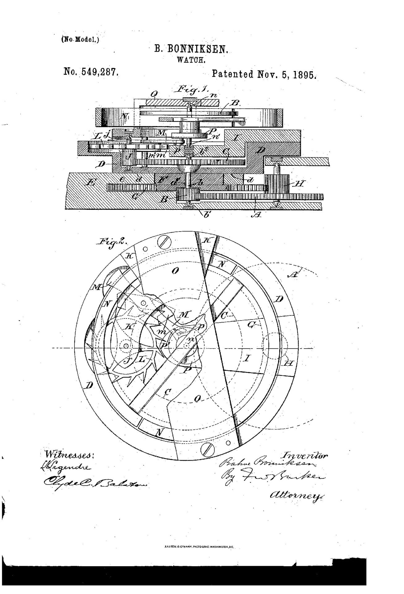
The karrusel diagram from Bonniksen’s 1894 patent
From a technical standpoint, the major difference between the two constructions is the use of fixed gears. The tourbillon is generally fitted over a large, fixed fourth wheel. As the cage is powered by the third gear, the escape pinion runs along the fixed gear, which powers the escapement and balance.
On the other hand, the karrusel employs no fixed gears whatsoever, instead the cage is powered by the third wheel’s pinion and the third wheel separately powers the fourth pinion.
The result is that the cage and fourth wheel spin independently in the same direction and around the same axis, but at decidedly different rates, as the fourth wheel has to turn faster to power the escape wheel. Due to this arrangement, the balance usually has to be offset from the gyration axis in order to accommodate the escapement.
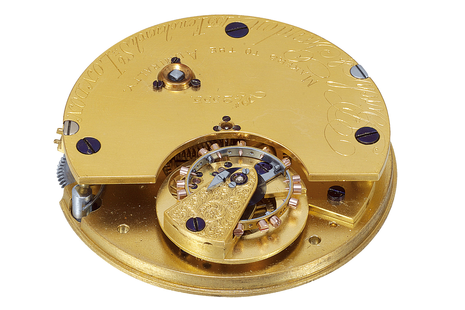
Bonniksen-stye karrusel movement, signed “Birch & Gaydon, Clockmakers in London”. Image – Antiquorum
However, the position of the balance relative to the axis of rotation is not a reliable marker of either construction, as an offset balance doesn’t necessarily mean the construction is a karrusel. The only definitive aspect for differentiating one from the other is the presence of a fixed gear of any kind: a construction incorporating such a gear (or ring gear) in the main plate is a tourbillon, and any construction that doesn’t feature any fixed gearing elements is a karrusel.
This conclusion brings the discussion back to the Freak. At the sight of the noticeably off-centre balance, one might be tempted to label it a karrusel. But referring back to the basic operating principles of the Freak, we find that the movement relies on a fixed interior ring gear to set the escapement in motion, which is assembled on a platform powered by a single pinion S. Thus the Freak is certainly a tourbillon, albeit one of a special breed.
A tale of two escapements
The Freak was famously the first timepiece to make use of silicon components in the movement. The initial designs from Ms Forestier-Kasapi didn’t feature nor require any silicon parts, and the architecture of the Freak itself doesn’t require any silicon components. Curiously, the original patent drawings for the Freak suggest a conventional Swiss lever escapement.
What prompted Ulysse Nardin to develop and employ this unexpected material was Dr. Oechslin’s desire to implement a new escapement. The inventor had already persuaded Schnyder to install a new escapement of his own conception into some prototypes, apparently meeting with much resistance.
This happened during the period when Omega was investing large sums of money into industrialising the Daniels Co-Axial, which it only achieved in 1999, proving that bringing a novel escapement to market was indeed a risky gamble.
Dr. Oechslin was eventually granted his wish during the late stages of the Freak’s development, when he was allowed to implement his experimental double wheel escapement in the equally experimental Freak movement. More significantly, the Freak’s experiment with a new escapement kickstarted the use of silicon in watchmaking.
The Dual Direct Escapement
Instantly reminiscent of the Breguet’s ecchapement naturel, the Dual Direct Escapement relies on two mirrored escape wheels, a small detaining lever and compound roller, complete with impulse pallets. And in an absolute first, the escapement was made of silicium, a form of silicon covered in a hard oxide layer.
Dr. Oechslin recounts he wasn’t aware of Breguet’s design at the time he devised the Dual Direct as he had limited knowledge with historical works. Instead he developed the escapement because the usefulness of this arrangement seemed plainly logical to him. Indeed, his idea differs in a some ways from Breguet’s, since the latter used pillars on his twin geared wheels to impart impulse, while the Dual Direct employs totally flat escape wheels.
Sadly, the escapement didn’t prove very reliable in practice, many owners having reported it to occasionally malfunction or freeze. That stemmed in part from the fact that the Dual Direct was trialled in a wall clock, and its use in a wristwatch proved problematic. As a result, most first-series Freaks had their escape wheels replaced with an updated version during service. Very few examples still retain the original Dual Direct Escapement wheels.
Despite its novelty at the time, there were good reasons silicium was employed in the Freak. First was a matter of the material’s hardness. An escapement is by design fast moving, and its action being correspondingly violent. As such, its parts need to be hard enough to retain a precise shape over time.
The next reason has to do with weight. One of the mirrored escape wheels is dragged along by its counterpart, which implies losses of efficiency due to inertia, as the mainspring has to accelerate not one, but two escape wheels. Lastly, the tight tolerances required demanded a manufacturing process that could consistently make small and precise components.
After unsuccessful trials with brass and aluminium wheels, silicium was suggested. Advantageously, silicium has a surface hardness of about 1,100 Vickers, almost 10 times that of brass, and a density of 2.33 g/cm³, less than a third the density of brass.
Moreover, silicium parts are produced via DRIE, a manufacturing process that allows for very precise flat components with perfect tolerances on a large scale. In short, silicium made the Dual Direct Escapement feasible.
A drawing of the Dual Direct Escapement – Ulysse Nardin
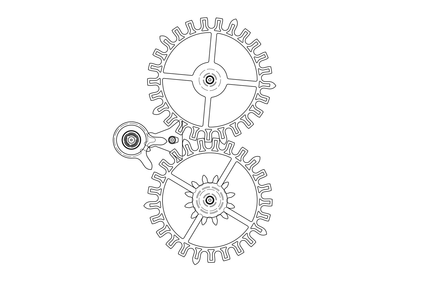
Extracted from patent EP1041459B1 for the Dual Direct Escapement, fig. a shows the escapement in its equilibrium position. We can notice the following main constituents: the two escape wheels 6 and 7, the lever- platform 21 and the mixed roller 1. The escapement is layered as follows: the purple-hued parts are on the same, lower layer, while the red-hued parts engage on a superior level to the first.
The two escape wheels each feature 25 teeth, but in two kinds of tooth profiles, namely types 13 and 15. There are five 13-type teeth and twenty 15-type teeth on each wheel.
The long teeth are spaced at intervals of 72° (360° divided by the 5 prongs). The 15 type teeth look as if a large part their addendums was cut off from the initial cycloidal shape of teeth type 13. The addendum is the portion of a gear tooth found above the pitch circle. The severed teeth are still fit to lightly engage with another gear. Tweaked in this fashion, the flat gear develops a sort of secondary plane of engagement within its main plane. It is clear that teeth 13 reach a bit further than the shorter teeth 15, so they can engage with a pair of impulse pallets 17 – 18.
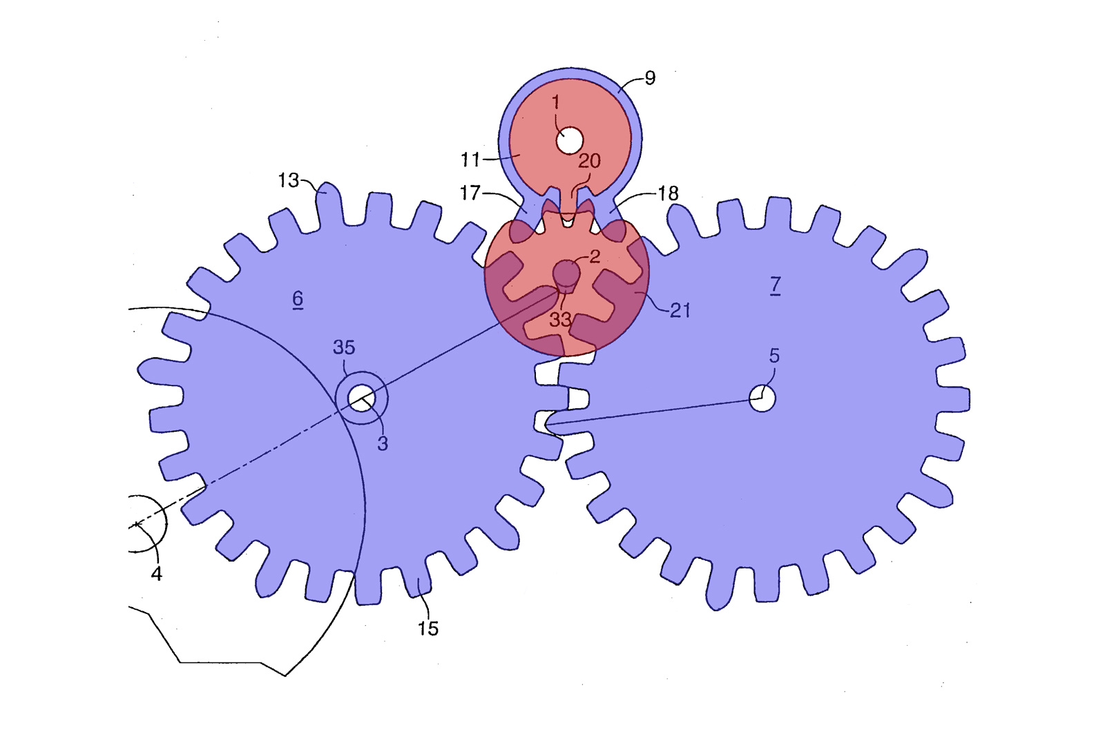
Fig. a
While Breguet opted for two split layers – a lower layer for meshing and an upper one for the actual parting of impulse – Dr. Oechslin brought down the thickness (and subsequently the weight and inertia) of his escapement by doing away with single-layered wheels. The impulse pallets 17 and 18 belong to the lower platform 9 of the roller 1. These two pallets are very much unlike their conventional counterparts. They don’t have the usual sharp, rectangular cut shape of traditional stones, nor are they made from ruby. Section 9 is practically a gear with only two teeth, conveniently arranged to serve as impulse pallets. Fitted co-axially with 9 is the safety roller 11, complete with tooth 20.
Said tooth behaves like a roller pin, mating with the two teeth of platform 21. Platform 21 serves as a sort of locking lever via its stud-like appendage 33. Fitted to the platform’s axle 2 and on the same level with the escape wheels, rocker 33 is designed to engage with the long teeth 13 of said wheels.
As mentioned, fig. 1 exhibits the system in its equilibrium state. Connected to pinion 35 of escape wheel 6 is another gear 4, belonging to the going train. If the barrel is wound, it would transmit power through the train to the escapement. Under the action of gear 4, driving wheel 6 would turn counterclockwise, entertaining wheel 7 in a clockwise motion of equal angular velocity (due to their 1:1 transmission ratio).
In fig. a the escape wheels appear to be in an arbitrary position. Regardless of their starting position, the two wheels don’t enter engagement with the locking rocker 33, since the latter is positioned neutrally by the idle balance wheel.
Eventually, coerced by the mainspring’s torque, the two escape wheels start turning. During their acceleration, either one of them is bound to engage impulse roller 9 through their respective long teeth 13. In our case a tooth (transversed by a line) of wheel 6 is set to fall into pallet 17, thus disturbing equilibrium and initiating oscillation.
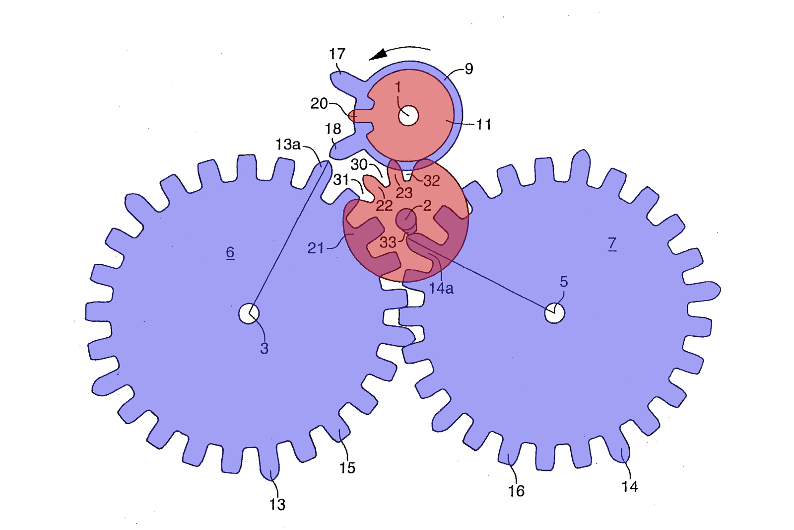
Fig. b
Fig. b shows the same system after the impulse was parted. The marked tooth 13a has noticeably advanced to a new position. According to the direction arrow, the balance has received the necessary impulse and has travelled its supplementary arc, and is now retuning towards its initial position under the restoring force of the hairspring.
The two connected escape wheels are locked by the rocker 33, which acts on tooth 14a of wheel 7. The locking is secured by the safety run between portion 32 of platform and safety roller 11. This is not entirely dissimilar to the action of the safety pin and roller in traditional lever escapements. While the notch 32 rests in contact with 11, platform 21 can’t turn, thus ensuring locking through the detent 33.
Turning counterclockwise, the balance-roller assembly 1 will first come into contact with platform 21 through tooth 20. On each side of said tooth there are two notches that allow teeth 23 and 22 respectively to fit in and engage with 20. From that moment of engagement begins the unlocking phase, closely followed by the drop.
The impulse, or drop phase can be closely observed in fig. c. The unlocking is complete, rocker 33 having moved out of the way of tooth 14a, allowing wheel 7 to advance. Tooth 14a falls and rolls against pallet 18, imparting impulse. The roller accelerates counterclockwise, dragging platform 21 clockwise and setting rocker 33 in place to lock tooth 13b of escape wheel 6. Notch 31 settles in contact with the safety roller 11, ensuring security of locking. The cycle then repeats.
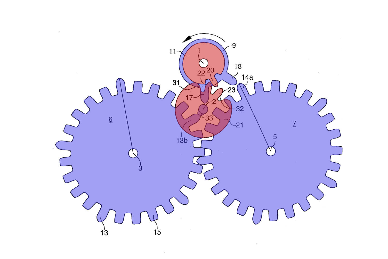
Fig. c
This arrangement features a 1.9:1 escape wheel to roller circumferential ratio and an 1:1 ratio between roller and platform. As plotted from the figures, rocker 33 is displaced a full 35° angle from its centred position during locking, which suggests a large, 35° unlocking angle, due to the aforementioned 1:1 ratio.
During the impulse phase each wheel travels 36° (half a tooth spacing), of which about 15° of run provide active impulse. Suggested by the 1.9:1 ratio between the escape wheel and roller, the former travels 28.5° during impulse. The locking action takes place at the same time with the impulsing, the blocking rocker 33 (along with platform 21) traveling another 35°.
Adding it all up, we get a total lift angle of 70°, which may appear awfully large at first, compared to the usual 52° angle of lift in Swiss lever escapements. However, since the actual impulse phase only takes about 28.5°, and the engagement during lock and unlock with the platform causes only reasonably feeble resistance, the disturbances on the balance swing remain minimal.
The following two figures show the Dual Direct as it was implemented in the Freak timepieces. The definitive structures differs slightly from the patent figures, especially in the balance roller and locking lever. The pictures suggest a more classical arrangement, crafted from an alloy, reminiscent of established escapement rollers with pin jewel (red). The overall simplicity of the system is otherwise retained.
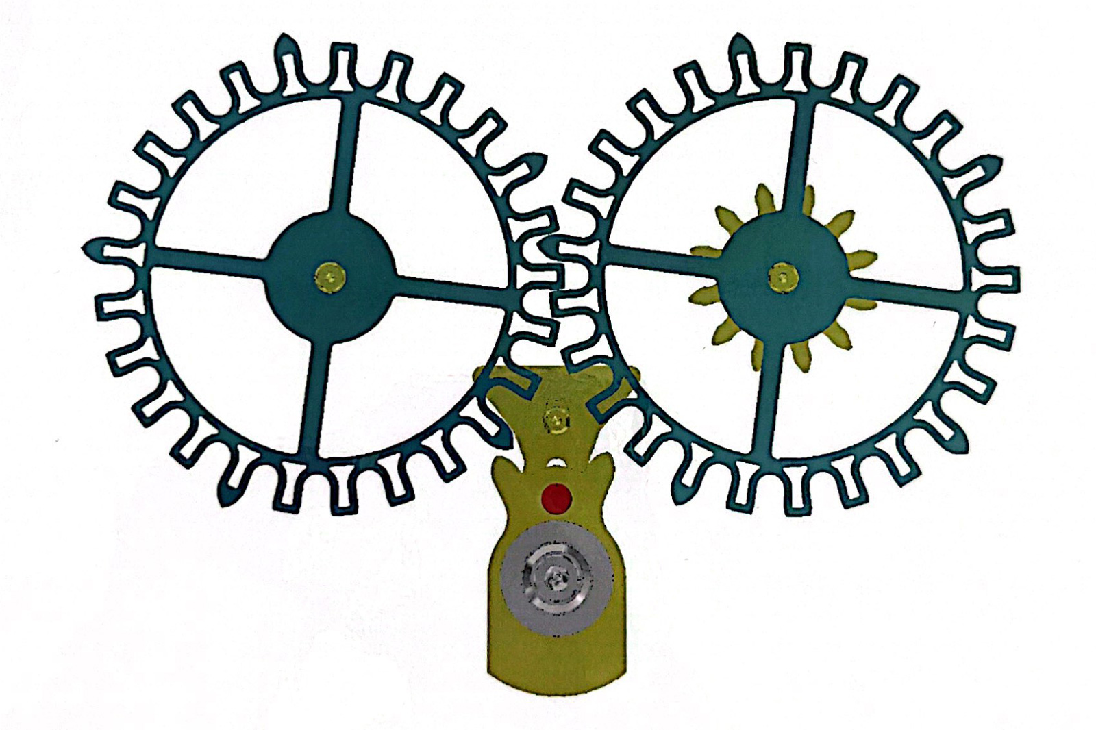
Dual Direct escapement diagram – Ulysse Nardin
The balance in the first series Freak beat at 3Hz, meaning the balance makes three full oscillations per second, or six vibrations per second. During one vibration each escape wheel advances 36°, for a total of 72° (or a full tooth spacing) each oscillation. This makes for an angular velocity of 3/5 turns per second for the two escape wheels. Comparatively, a Swiss lever escape wheel only turns once every three seconds, almost twice as slow as the two Dual Direct escape wheels.
The generous spacing between the active teeth also means they don’t meet with the impulse teeth right after the unlocking, so there is a fair portion of “dead” travel before the actual drop takes place.
Another particularity of this escapement lies in the absence of draw. The draw angle generally fulfils a safety function. In a Swiss lever for example, the locking face of the pallet rests on the escape wheel teeth at a certain offset angle, which binds the pallet to the escape teeth. The draw is what offers resistance to unlocking and security during the large supplementary arcs. This concept is thoroughly absent from the Dual Direct Escapement, which suggests the locking action is shallow and unsafe.
Along with the dubious locking, the interplay between the driving and driven wheel is another great disadvantage. The rules of gear engagement are being heavily broken by the different tooth lengths, which give for different penetration depths, resulting in periodically uneven meshing.
Intrinsic to the construction of “natural” escapements, the driven wheel is under no tension when the driving wheel is locked, so it is allowed a slight flutter. Combine that with the troubled meshing and the result is highly unequal and inconsistent impulses. However, it is assumed that the very tight production clearances in DRIE should, in theory, ameliorate the gear interplay to an extent.
As mentioned, this first conceptual escapement performed poorly in the original 2001 series Freak, which led to most pieces being retrofitted with a second, more stable version during service. The Dual Direct Escapement was completely reworked, with the second-generation version retaining only the double wheel architecture. We will detail that in the second part of the Freak saga.
This was brought to you in partnership with Ulysse Nardin and its retailer The Hour Glass.
Back to top.