The Ulysse Nardin Freak – The Saga of a Scientific Timepiece Part III
From silicium to Grinder.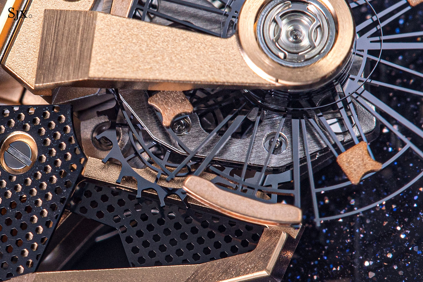
An outlandish concept that originally sprang from the mind of Carole Forestier Kasapi, the Ulysse Nardin Freak of 2001 was perfected by Dr Ludwig Oechslin and then made reality thanks to the advent of silicon in watchmaking. Lightweight and magnetism resistant, silicon was used for the escape wheels but that was only the beginning of the story.
[This story, the third and final instalment in the series, details the history of silicium, the proprietary Ulysse Nardin silicium hairspring, and the patented Grinder rotor. The Saga of a Scientific Timepiece Part I covers the origins of the Freak, from its conception to realisation, as well as its distinguishing characteristics, namely the inventive movement construction and unique escapement. Part II deals with the evolution of the unique, high-performance escapement.]
Silicon, Silicium, Silinvar
Now used interchangeably with silicon, silicium is actually French for “silicon”, but now it is also used as the trade name for the proprietary form of silicon used by Ulysse Nardin for movement components, namely silicon with a hard oxide outer layer that gives the material thermocompensating properties.
Silicium was developed by Swiss scientific institute Centre Suisse d’Electronique et de Microtechnique (CSEM) in collaboration with Ulysse Nardin. Notably, the material is also known as Silinvar, which resulted from a separated but related CSEM project backed by a consortium made up of Rolex, Patek Philippe and Swatch Group. As a result, prior to the patents relating to silicium in 2022, only Ulysse Nardin and the brands that made up the latter consortium were able to incorporate silicon parts in their movements.
Unsurprisingly given its status as the pioneer of silicon in watch movements, Ulysse Nardin is one of the handful of watch brands that controls its own silicium-part manufacturing. Such components are produced at Sigatec, a silicon micromechanical specialist it partly owns.
Etching a silicon wafer at Sigatec, the silicon manufacturing specialist owned by Ulysse Nardin. Image – Ulysse Nardin
The origin story
Although now widespread in watchmaking, silicon was exotic when it first appeared in the Freak in 2001. Silicium originated just after that, when CSEM recognised the commercial value of its silicon etching technology known as LIGA, particularly for its applications in horology. In the autumn of 2001, Dr Oechslin was contacted by André Perret of CSEM, seeking to know if LIGA (short for the German phrase LIthographie Galvanoformung Abformung) could be used to make silicon components aside from the escape wheel.
Ever the scientist, Dr Oechslin pondered the question and came to a realisation – hairsprings. With its hardness and partial elasticity, silicon could perform well as a balance spring. Moreover, it could be shaped in the form of a flat spiral more accurately and easily compared to the delicate process used for coiling wire alloy springs like the industry standard Nivarox.
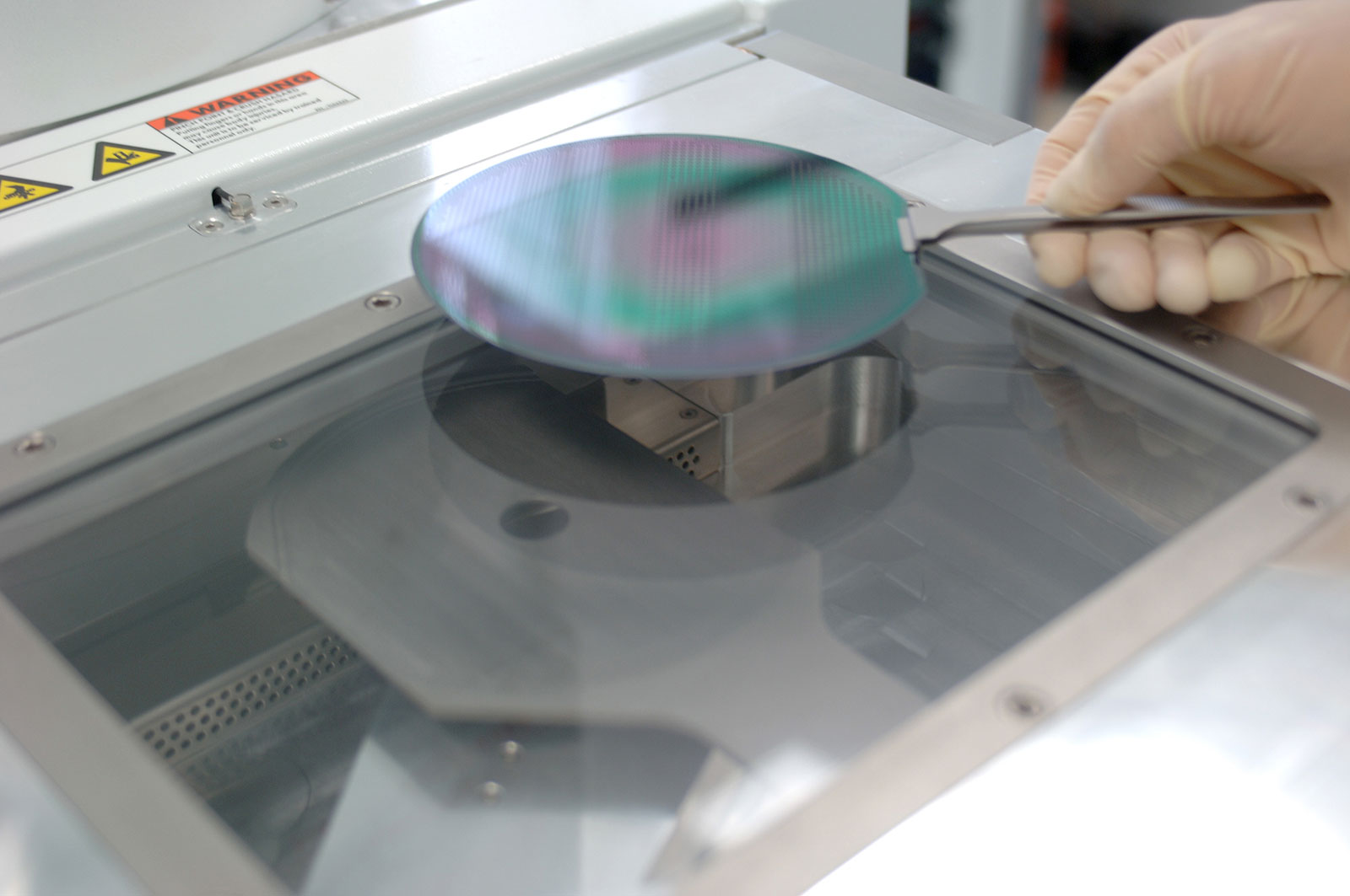
Dr Oechslin also noted that a silicon spring could be designed to conveniently incorporate the inner collet, making assembly easier for the watchmaker. In early 2002, in collaboration with CSEM, Dr Oechslin created the first silicon hairsprings, which he installed in robust and simple Unitas movements to test.
The first silicon hairspring. Image – ‘Silicon and Watchmaking, report of trials with silicon hairsprings at the Musee International d’Horlogerie’ by Dr Ludwig Oechslin, MIH
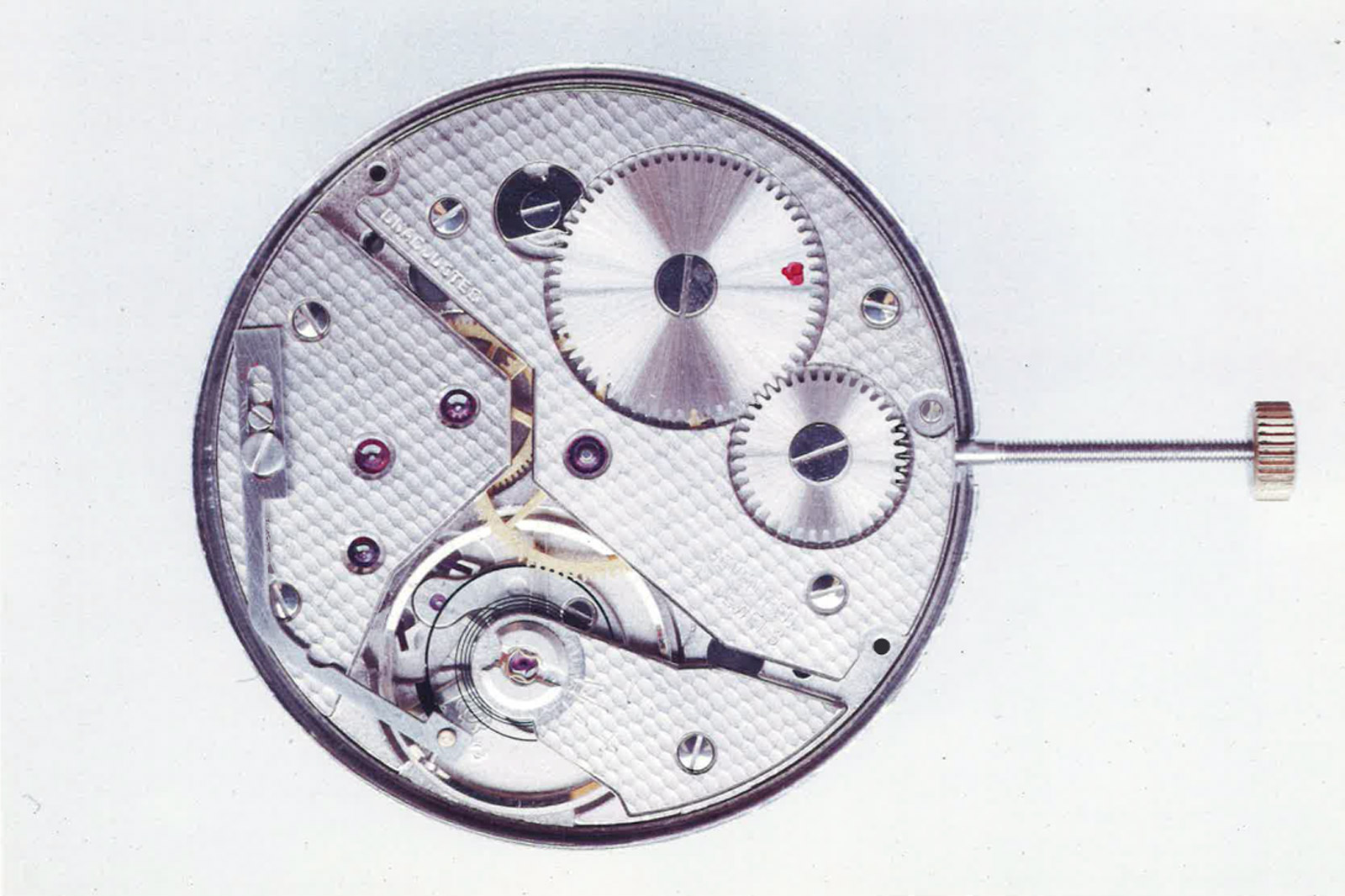
Unitas movement equipped with an experimental silicon hairspring. Image – ‘Silicon and Watchmaking, report of trials with silicon hairsprings at the Musee International d’Horlogerie’ by Dr Ludwig Oechslin, MIH
The results were mixed, as while the hairsprings were dynamically working as expected, they were not able compensate at all for any changes in temperature. Dr Oechslin noted a 106 second error over a temperature variation range of 31°C. The issue was eventually addressed by coating the springs with a fine layer of silicon oxide, which has an advantageously inverse thermo-elastic coefficient in relation to raw silicon, resulting in the material now known as silicium (or Silinvar).
A diversion into isochronism and overcoils
More than just a replacement for Nivarox hairsprings, silicium hairsprings offer valuable advantages over their alloy counterparts. Firstly, silicium can be formed into any shape, so it can be made to include the collet (the inner attachment point that fits on the balance staff) and outer attachment point, all as a single piece. This means more manufacturing accuracy and less assembly operations required of the watchmaker. Secondly, a silicium hairspring can be designed to be inherently more isochronal, with the etching process able to reproduce such a design exactly.
Isochronism is the ability of an oscillator to retain the same vibrational period, independent of its amplitude. It means that a balance swing should take the same amount of time regardless of how large or small the arc travelled. In clocks and watches, as the mainspring unwind it sends less and less torque to the escapement, causing the balance to oscillate at noticeably lower amplitudes. This makes isochronal hairsprings highly desirable, as the balance then retains the same vibrational period (such that it keeps good time) regardless of the smaller arc travelled and the mainspring’s fading state of wind.
Mathematically, a sprung balance is an isochronal model, as its oscillation period is a function of its polar moment of inertia and restoring torque exerted by the hairspring, independent of its amplitude. In practice however, pivot friction and the uneven development of the hairspring lead to gross isochronal faults that are responsible for timekeeping deviations.
While pivot friction is manageable to an extent, watchmakers have long tried to address the issue of uneven development in balance springs. The issue itself is pretty straightforward: as the hairspring is fitted to a fixed stud on the balance cock, it isn’t allowed to evenly expand or contract, as the fixed stud impedes the “breathing” on one side. The phenomenon can be clearly observed in the two figures below, which show a hairspring wound and unwound, respectively, by 330°, mimicking a full oscillation. This uneven development continuously shifts the spring’s centre of gravity and exerts unwanted pressure on the balance pivot, making the oscillator anisochronal.
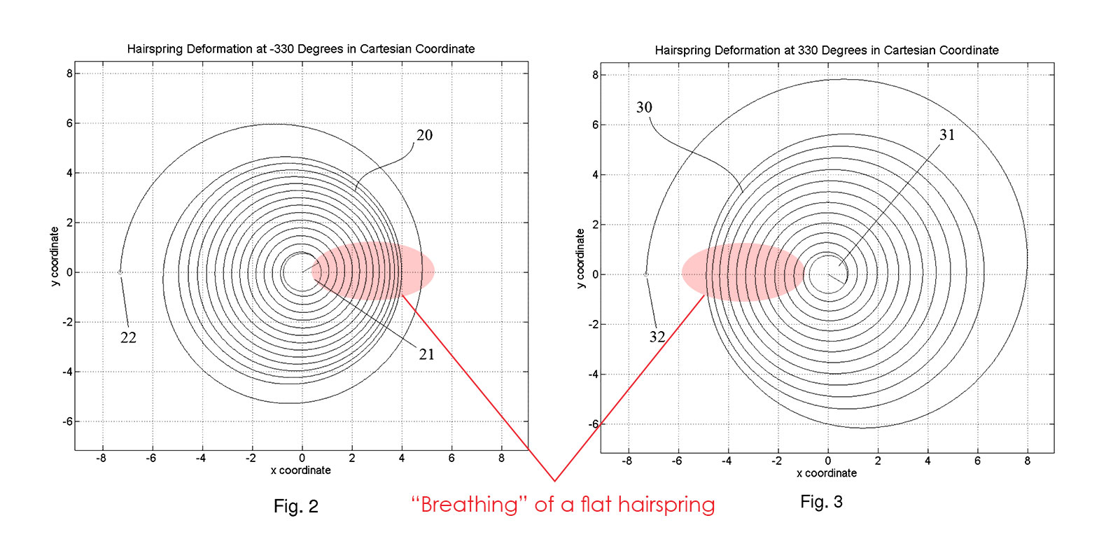
The “breathing” of a regular hairspring. Image – Patent US9658598B2 by Master Dynamic
A long established solution is the Breguet overcoil. In a Breguet hairspring the outermost coil of the spring is raised above the rest of the coils and abruptly bent inwards; the stud is then fitted to the raised end of the coil. This creates a noticeable end curve that breaks the regular pattern of the spiral.
The result is a spring free to expand and contract under the raised end curve, unimpeded by the fixed point. As the name suggests, it was invented by Abraham-Louis Breguet, who was himself inspired by his English counterpart John Arnold’s work on cylindrical hairsprings. The overcoil is sometimes referred to as the Philipps curve, after the celebrated mathematician Edouard Philipps, who devised a formula for forming the theoretically perfect overcoil.
Very visible Breguet overcoil of a Rolex Parachrom Blu hairspring
The Breguet overcoil is difficult to execute, as it generally requires an experienced watchmaker to bend it by hand. That’s why a hand-formed overcoil remains a mark of craftsmanship, even among high-end timepieces. Modern technological advancements, however, have allowed brands like Rolex to develop purpose-built machines capable of forming perfect overcoils automatically.
From a practical standpoint, the greatest drawback of the Breguet hairspring is the vertical space required for the raised length of the coil, which can be problematic for slimmer movements. In spite of manufacturing advancements, the Breguet-Phillips overcoil enjoys only limited use in mass-produced timepieces, with notable exceptions including Rolex calibres and the IWC 52000-series movements.
Another way of making a hairspring isochronal was devised by the Michel brothers in Belgium. They proposed a flat hairspring with a varied thickness along its length (fig. 9), which would force the spring to “breathe” concentrically by rendering the thicker section stationary. Their trials were surprisingly successful, proving their theory right. However, making one-piece wire alloy hairsprings with stiffened sections was, and still is, a cumbersome task much too difficult for any kind of mass production.
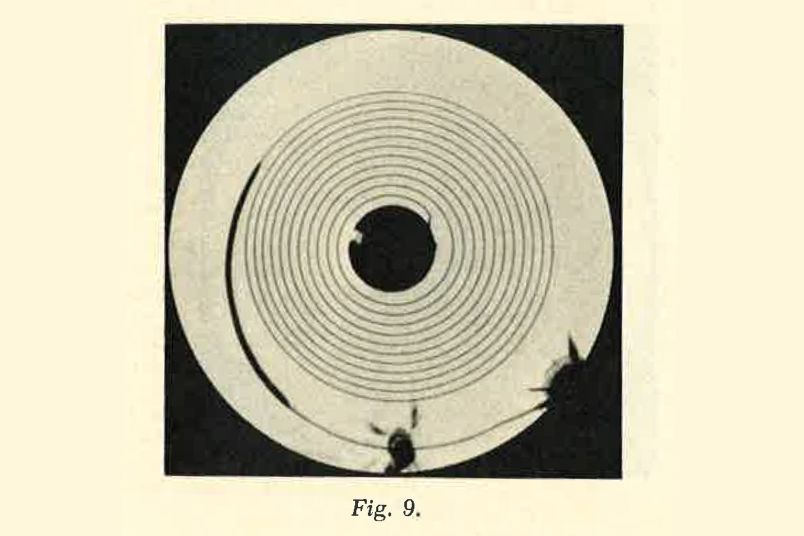
A prototype “Michel” hairspring with a stiffened segment. Image – ‘Spiraux plats concentriques sans courbes’ by Emil and Gaston Michel
The unique Ulysse Nardin hairspring
Returning to silicon, it becomes obvious that a Breguet overcoil cannot be easily created in silicon as it has a three dimensional structure, while the etching process for silicone only allows for two dimensional parts. The Michel brothers’ method, however, is perfectly suited to silicon: it only requires the coil thickness to be varied while retaining a flat structure, which is easy to achieve accurately with the etching process.
Along with the Swatch Group, Rolex and Patek Philippe, Ulysse Nardin was licensed to produce hairsprings in temperature-compensating silicon, silicium or Silinvar in other words, under the patent filed by CSEM. While the patent only covered the basic wafer production method of springs and the application of an outer coating of silicon oxide, it didn’t explicitly mandate a particular geometry. Conveniently, each company was free to experiment and develop its own hairspring shapes.
The first commercially-available Ulysse Nardin silicium hairsprings featured a thickened and stepped outer portion for concentric expansion and contraction. Patented by longtime Ulysse Nardin engineers, Pierre Gygax and Stephane von Gunten, the hairspring was a direct adaptation of Michel brothers invention.
Not long after, Patek Philippe began rolling its own Silinvar hairspring dubbed Spiromax, which also employed stiffened portions to improve isochronism. Rolex’s Syloxi hairspring similarly employs thicker outer coils for improved geometry, so it’s safe to say that Michel brothers’ method for flat, isochronal springs has become the de facto geometry for most silicon hairsprings.
More refined and elegant than the early example of the Ulysse Nardin silicium hairspring is the latest iteration designed by Stephane von Gunten, which is now found in the majority of current Freak models. Compared to previous examples, this hairspring features a large and noticeably eccentric end coil, lending the whole a vaguely oval shape. This design is set apart from previous executions because it tackles isochronal defects via sheer geometry rather than stiffened portions, making it an altogether novel contribution Ulysse Nardin brought to horology.
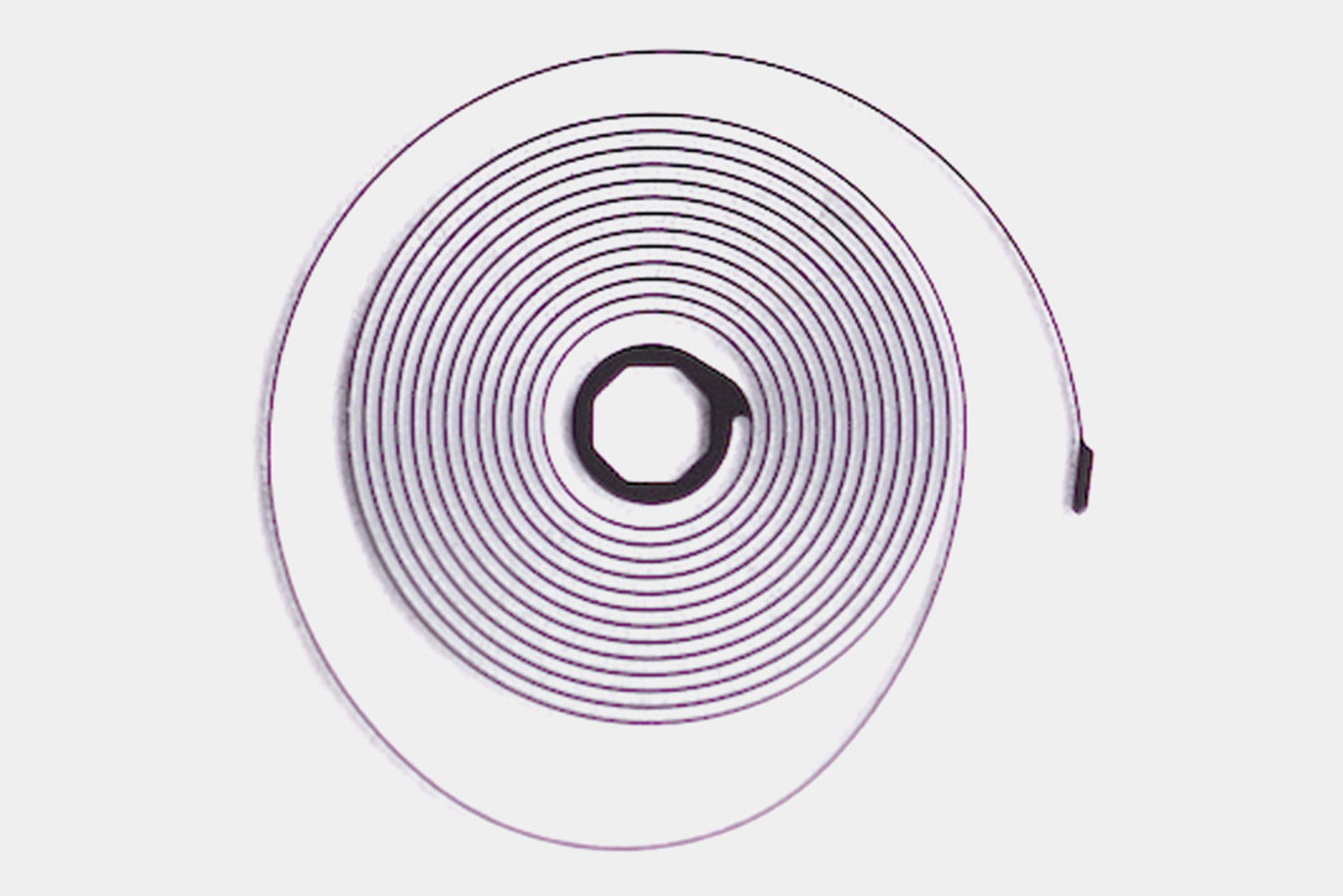
Image: Sigatec SA
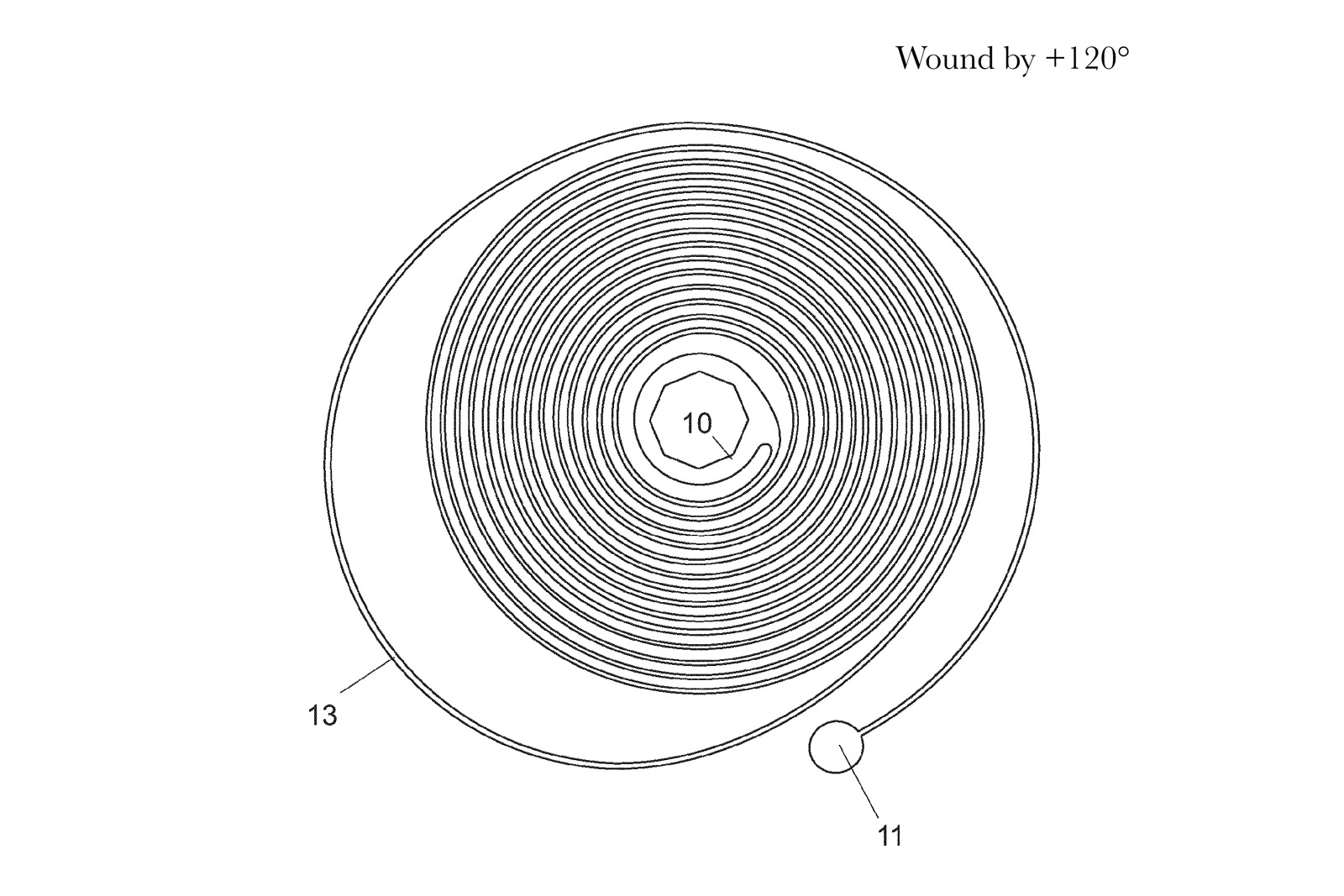
The most common of spiral forms, known as Archimedes’ spiral, is defined in polar coordinates by a linear function dependent on a developing angle. In brief and simple terms, it means that the radius from center to any given point is proportional to the angle between origin and said point. This gives the spiral its sweep and regular crescendo, with each coil getting constantly larger than the previous.
In fig. 10, the inner coils make up a regular spiral, with a constant distance between them. The last coil however breaks that uniformity and forms a large and asymmetric curve 13. Mathematically, it means that the outer portion of the spring is defined by a non-linear function, which behaves differently from its previous linear counterpart – think quadratic equations. This last coil seeks to cancel the isochronal errors caused by any eccentric breathing of the inner spring.
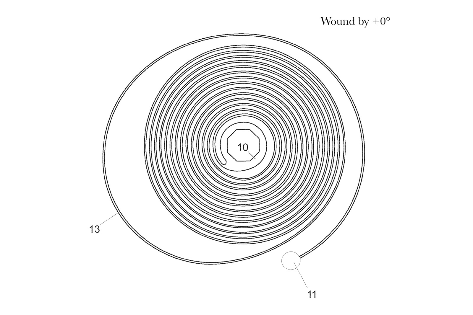
Figure 10. Outline of an Ulysse Nardin hairspring in a neutral position
The non-linear function was devised with modern technology, namely computer simulations. Ulysse Nardin’s engineers simulated the uneven expansions and contractions of a flat spiral with a chosen attachment point. Then, keeping the attachment point stationary, the team computed and modelled several end curves whose restoring torque would counteract the defective breathing, until they found the suitable non-linear function. The resulting hairspring geometry keeps the gravity center coincident with the gyration point, regardless of how much the inner spiral contracts or expands.
This is a novel approach to isochronal correction in hairsprings and can be regarded as more refined and sophisticated than the Michels’ method, aided by today’s technology of course. Regardless, the two solutions remain similar, as both rely on uneven elastic forces throughout the hairspring.
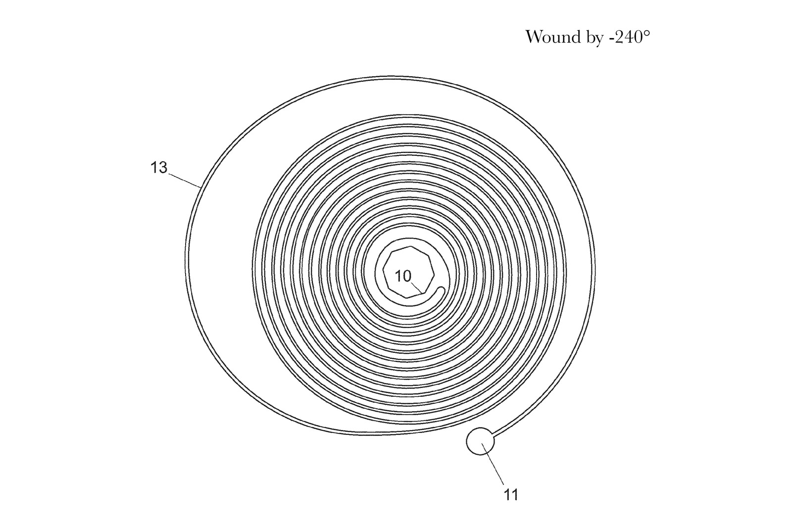
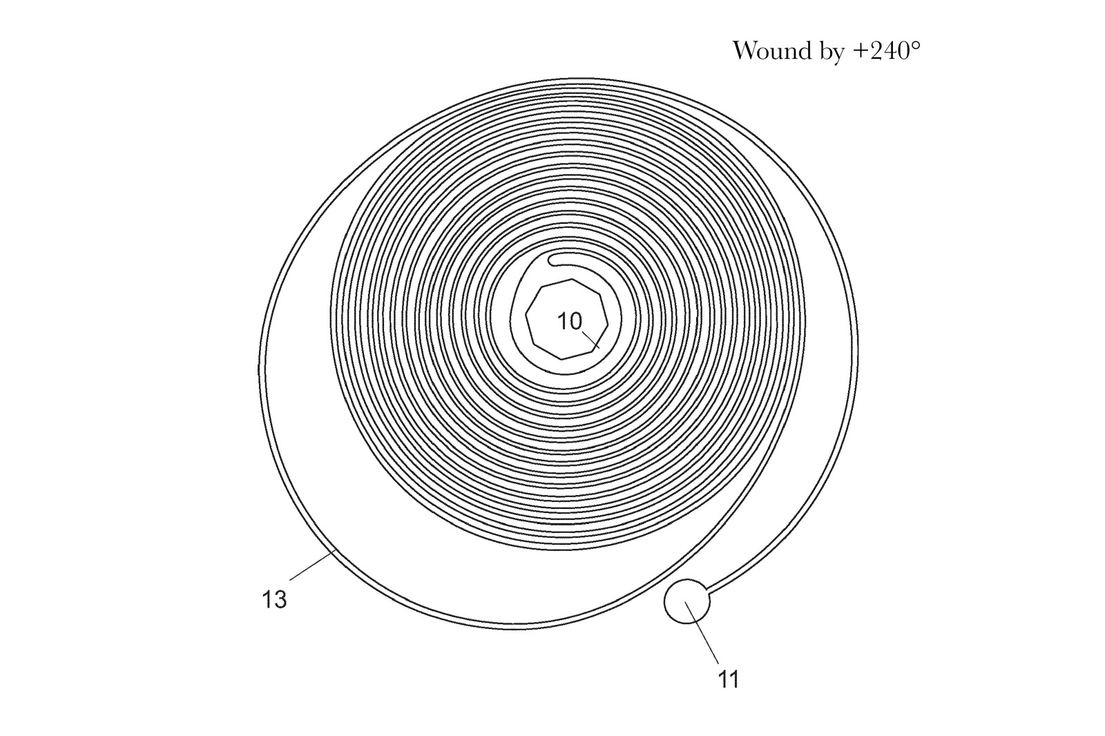
The following figures show a simulation of the modelled Ulysse Nardin isochronal silicium hairspring, run through different winding states that mimic the oscillations of a balance. The inner coils are shown to breathe concentrically, with only sensible deformations towards higher amplitudes. The figures also reveal how the spring incorporates an inner collet and the attach point for the stud, meaning it’s much easier for the watchmaker to pair the spring to a balance and then install it into the movement.
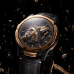
Ulysse Nardin has since moved beyond the hairspring and escapement in its use of silicium. Some later Freak models also sport a silicium balance wheel.
Traditionally, balance wheels are crafted from metal alloys specifically formulated to be temperature-compensating and magnetism-resistant, such as Glucydur.
Silicium, namely silicon with a silicon oxide outer layer, also compensates for temperature-related deviations thanks to the opposing physical reactions of silicon and silicon oxide to changes in temperature. Furthermore, the material is inherently impervious to magnetism, which makes it an appealing proposition for balance wheels.
Using the same high-tech etching methods used for escape wheels and hairsprings, Ulysse Nardin now manufactures a lightweight silicium balance wheel with nickel weights installed close to the rim, an example is found in the Freak S.
The ideal set up in any sort of pendulum is to concentrate most of the total mass far from the gyration point. The low-density silicium frame provides for a light yet sturdy structure, while the heavy nickel weights work as active mass for generating inertia and are positioned from the axis of oscillation.
The moment of inertia value for the silicium-nickel balance used in Freak One and S models is a relatively low 8 mg.mm2. This value stems from the heavy rotating carousel characteristic of the Freak, which is incompatible with a larger inertial moment, so the lower 8 mg.mm2 fits the purpose.
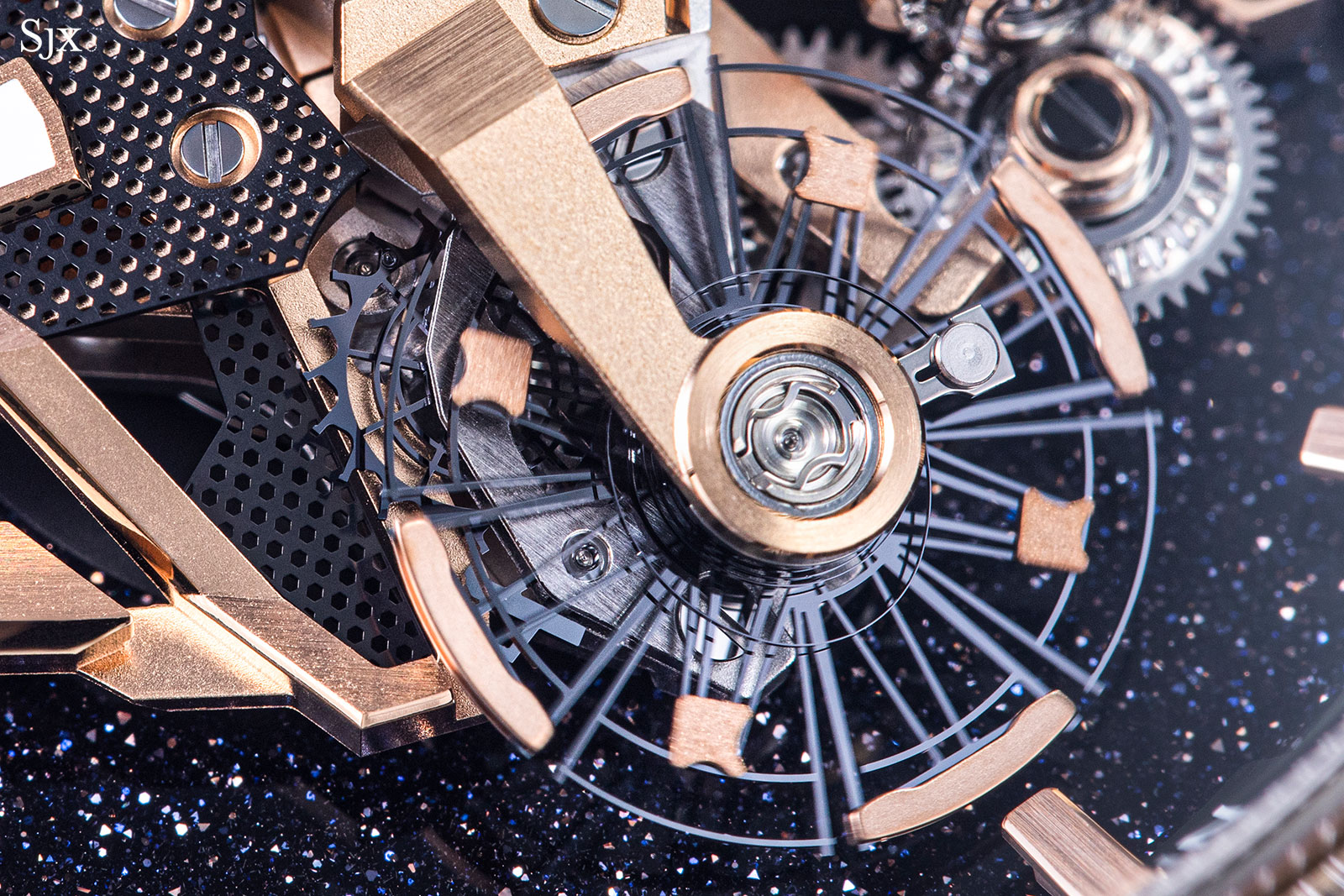
Silicium frame balance wheel with nickel ingots on its rim; the arrow-shaped weights are used for regulation
Dual balance wheels
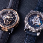
All of the innovations described above – most of which originated in the first Freak of 2001 – are now found in the Freak S. A significant departures from traditional Freak architecture, the Freak S is equipped with twin independent regulating organs, both driven by the same large mainspring that fills the case.
The goal of the twin-balance set up is superior accuracy, as the two balances are connected by a differential gear set that averages out their respective rates. The same principle is famously used in the Philippe Dufour Duality and the more recent MB&F LM2. The difference between the Freak S and most other twin-balance movements is the implementation of the differential: the Duality and LM2 are constrained by classical movement layouts and employ flat differentials that mostly blend in with the going train, while the Freak S relies on the more three-dimensional spherical differential that is more visually striking.
A differential set is a sort of planetary gear train with three drive shafts: one for power input and two for the outputs. The special propriety of differentials is that the input shaft has a speed equal to the average of the two outputs. The construction allows the gear set to provide the two output shafts with independently variable torques and speed from the same power source.
Logically, the most common use for differentials is in car transmissions, where they allow the wheels on the same axis to turn at different rates while cornering: the wheel facing the outside of the corner always travels more than the one facing inwards. This happens as power to the wheels needs to be split accordingly for optimal traction.
In a way, the differential in the Freak S does the same thing, allowing the two balances to have independent behaviour, while transmitting the averaged rate of the two escapements further down the gear train. It is able to do this because any differential gear train receives feedback from each output and then computes how much power each requires individually. A simple diagram of a basic differential setup is shown in the figure below.
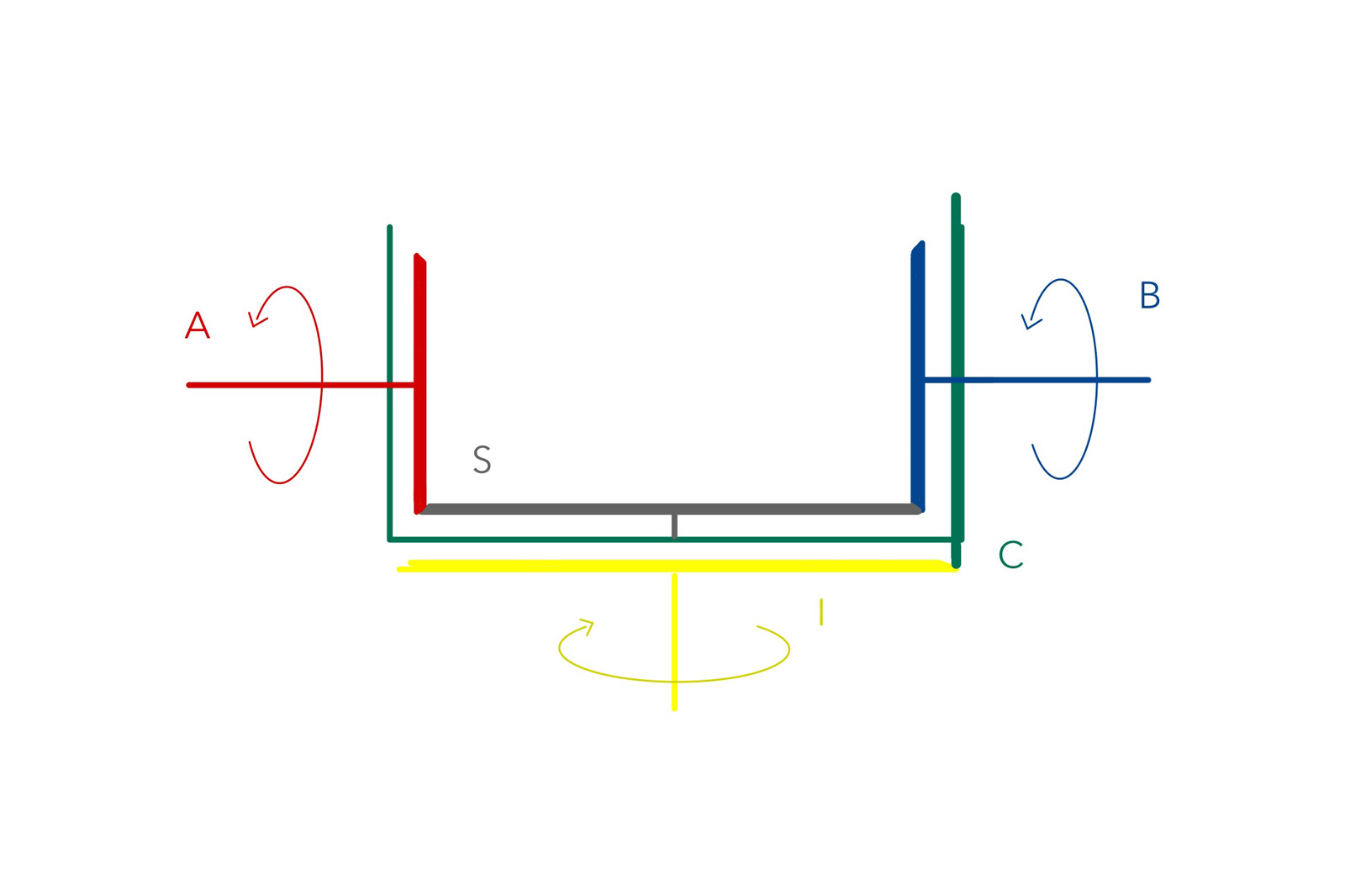 The input gear I (yellow) connects to a toothed rim of the carrier C (green) The I to C transmission ratio is usually 1:1. The carrier works like a cradle, holding the two individual outputs A and B (red and blue, respectively) together with the intermediary gear S (grey). Assuming powers flows through I to the carrier C, the differential is set in motion.
By default, gear S doesn’t move and A and B have the same speed as the carrier C, as if they were rigidly connected to it. However, if a braking action is impressed on A for example, S runs along A’s teeth and accelerates B, which already has the carrier’s speed. One output is sped up by the same amount the other is slowed down and vice versa. At any given moment, the average of the two output speeds is the input’s speed.
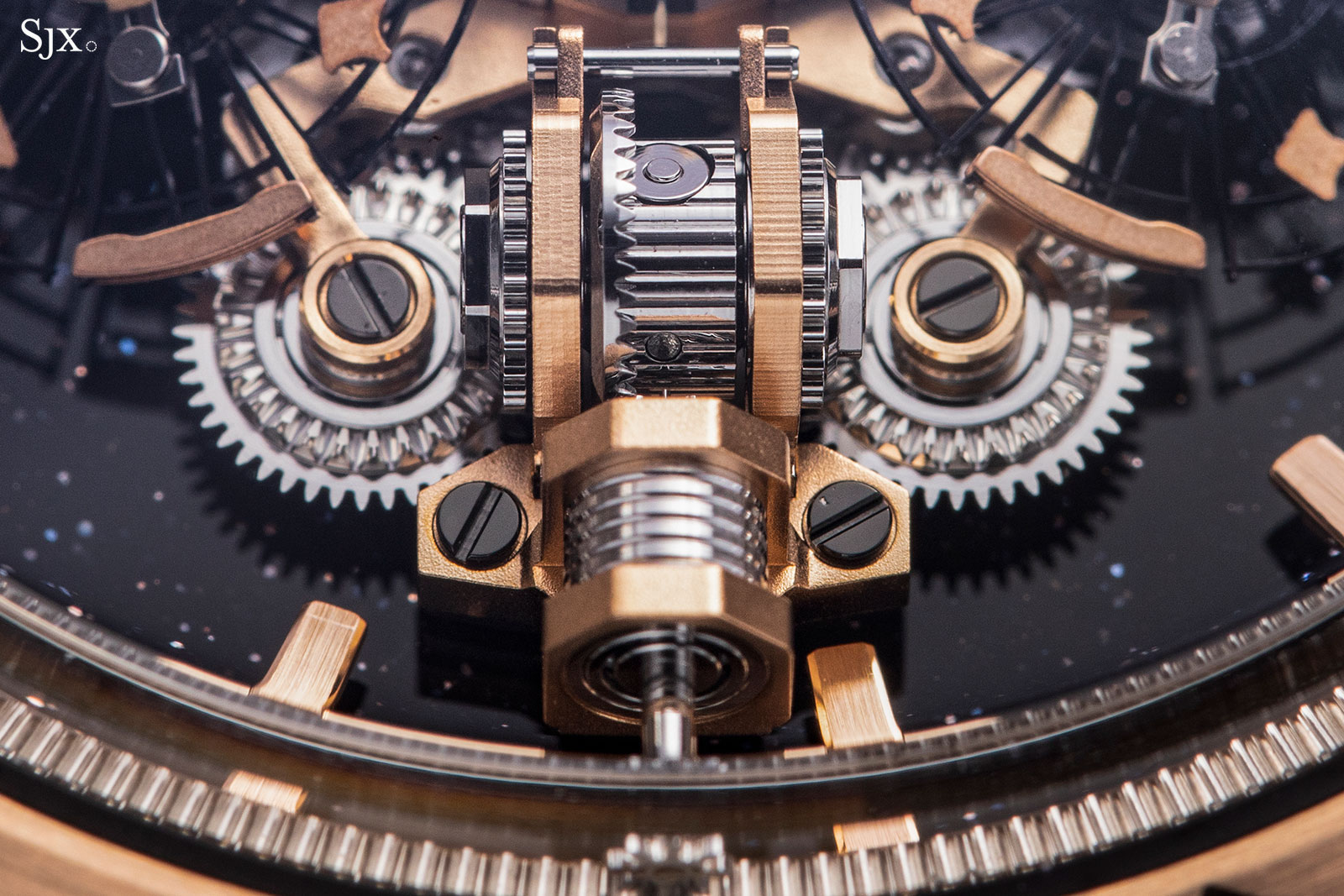
The spherical differential with one input and two output shafts on either side
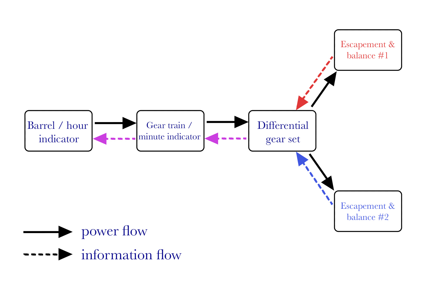
In the specific case of the Freak S, the differential is unable to speed up or down any of the outputs, as the balance sets the escapement’s rate. In consequence, the input speed is influenced by the two outputs, not the other way around. The double function of the differential in the Freak S is thus to source power to the twin escapements and compute their respective rates. The torque transfer can be described as power flow, while the compound velocity set by the twin escapements is information flow, because it commands the time display. The following diagram sums up these two functions. In typical Freak fashion, the barrel cover doubles up as an hours hand and the main platform works as a minutes indicator.
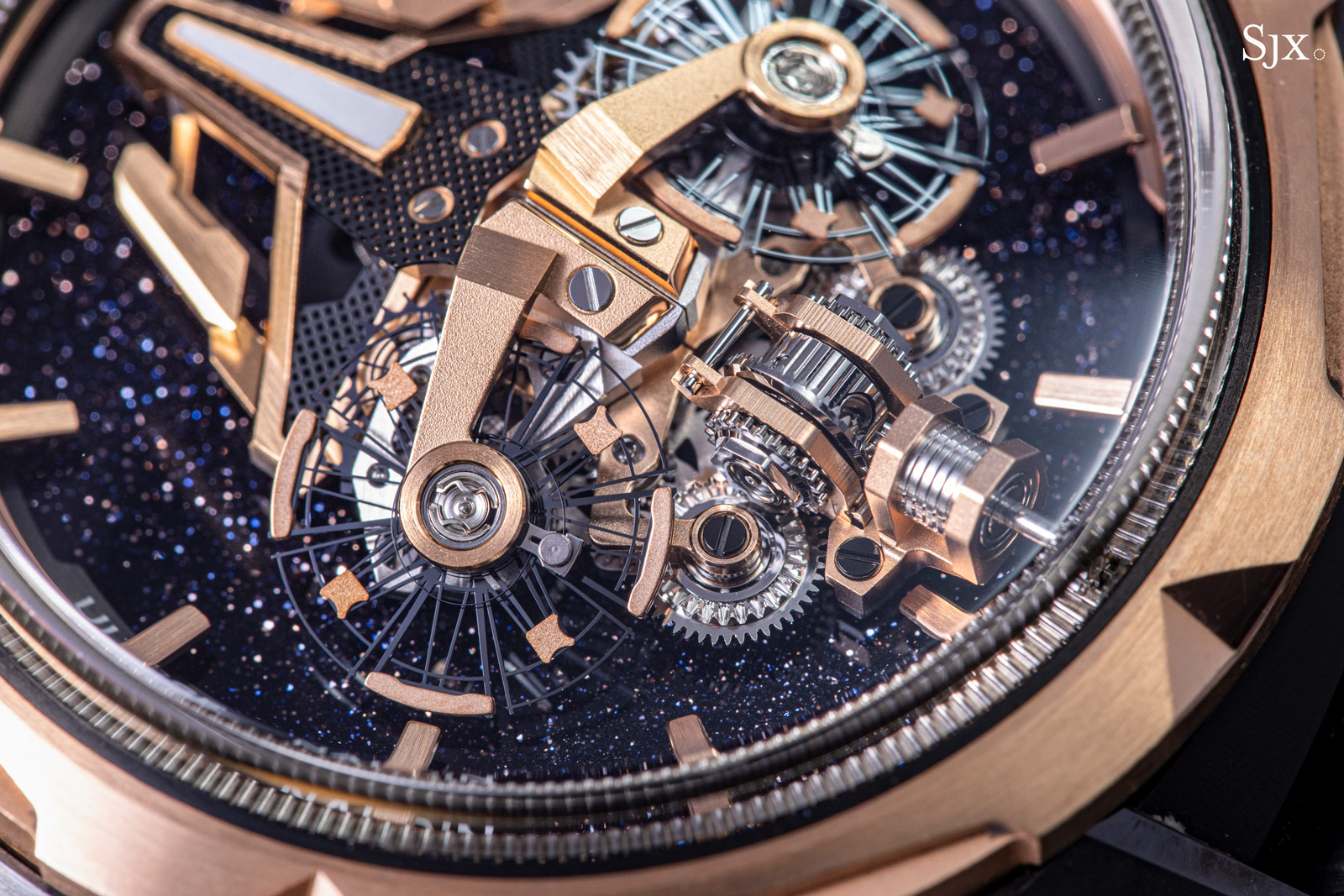
Another unique feature of the Freak S is the two balance wheels mounted at an incline, so each is positioned at an angle to the other. Due to this position, the two balances are affected by gravity differently at any point in time, leading to different positional errors in their respective rate. In theory, the individual defects of each balance’s rate will be averaged out by the differential, leading to a more consistent and stable aggregate rate across all positions.
As the minute carousel’s speed of rotation set by the output shaft, the time display is practically the average of the two escapements. The principle is theoretically sound and appealing, but such a complex timepiece is bound to suffer from mechanical-derived inconsistencies, such as increased gear play, friction and pivot strain due to the heavy revolving platform. The system is also power intensive, requiring sufficient torque to maintain two oscillating organs. That’s likely the reason why the balance frequency is only 2.5 Hz, similar to classical watch movements, instead of the 4 Hz of most Freak movements.
Reinventing winding
Although the winding mechanism is not as central to the movement as the escapement or oscillator, the self-winding system of the Freak stands out as one of the most interesting inventions associated with the model, although it came long after the watch was devised.
The original Freak and all subsequent iterations were almost entirely manually wound, both as a matter of necessity and convenience. The architecture imposed a certain height on the movement, making the addition of an efficient automatic mechanism problematic without excessive thickness.
Moreover, the large mainspring of the Freak – large enough it fills almost the entire case – would require an exceptionally powerful automatic mechanism, which was not readily available at the time. A practical solution only arrived in 2017 with the first self-winding Freak, the InnoVision 2 concept watch that featured the Grinder winding system. This subsequently evolved into the Freak Vision of 2018, a serially produced model containing many of the innovations found in the concept watch.
The Grinder in the Freak Vision
Conventional automatic winding systems largely fall in two categories: reverser gears and Magic Lever.
Probably the most common, the reverser wheel system is found in a wide range of Swiss movements, from basic ETA movements to latest generation Rolex calibres. The system relies on a complex train of reversing gears that transform the bi-directional, intermittent rotation of the rotor into a uni-directional, high-torque winding motion.
The system is regarded as consistent and reliable, although not highly efficient. When the rotor changes direction, some of its kinetic energy is lost due the reversers’ construction. Moreover, the fast moving parts usually require extensive lubrication. Because of the complexity, reverser wheel winding usually takes up substantial vertical space on top of the timekeeping portion of the movement, resulting in thicker constructions.
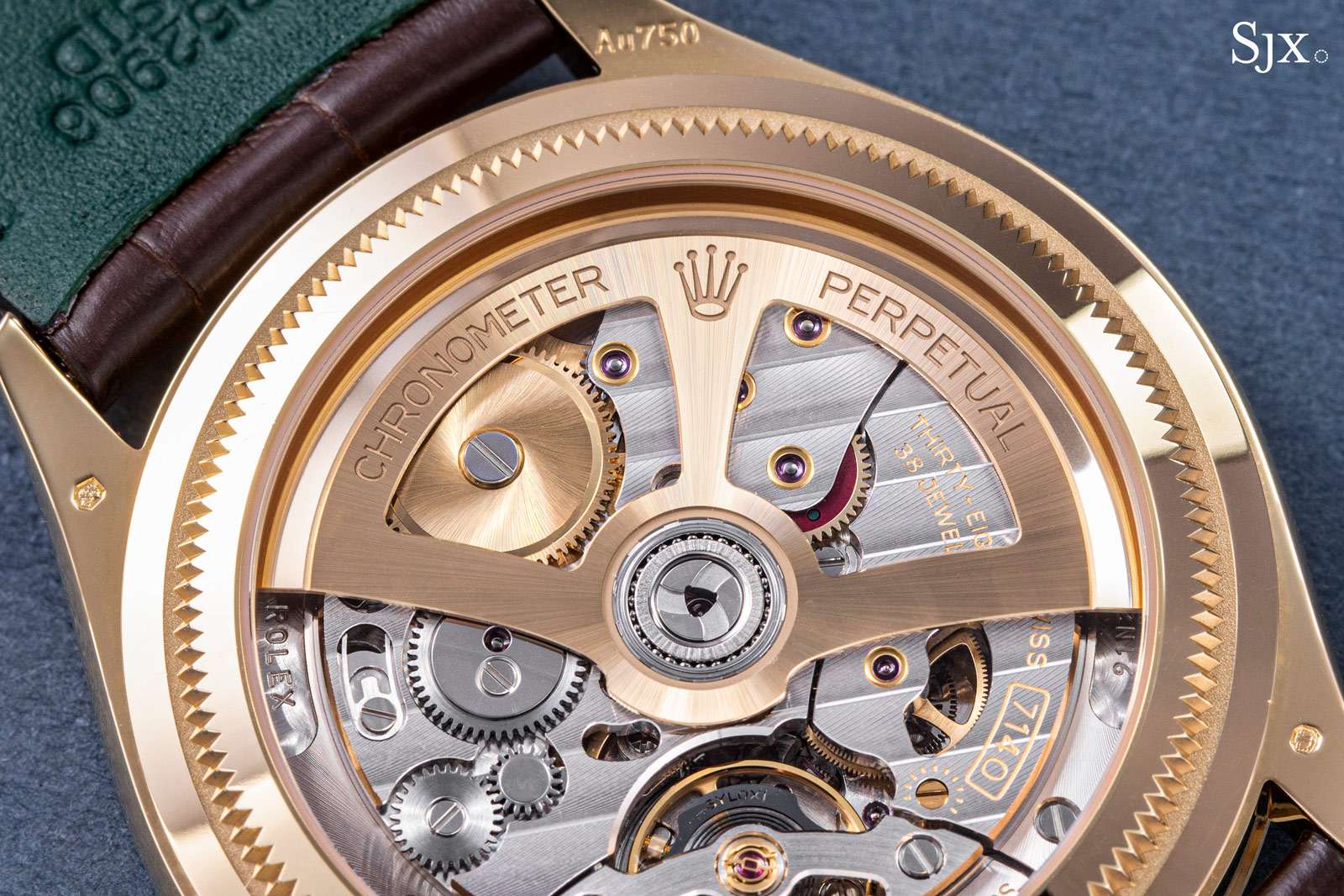
One of the reverser gears, featuring the signature red coating, is visible in the Rolex cal. 7140
Invented by Seiko in 1959, the Magic Lever was conceived to improve winding efficiency in wrist watches in a cost effective manner. The invention differs wildly from the reverser system favoured by the Swiss, being much simpler but conversely more efficient. In the decades since, the Magic Lever has been adopted by Swiss watchmakers, ranging from Lemania to Ulysse Nardin and even haute horlogerie calibres from Vacheron Constantin.
The Magic Lever gets its name from a Y-shaped pawl that connected to the winding gear. Featuring a beak on each of its ends, the pawl embraces the winding wheel, allowing the beaks to mesh with the winding wheel’s teeth. The winding wheel is linked to the barrel ratchet and can only turn in one direction. The rotor sports an eccentric cam on its arbor that is pivoted the pawl.
When the rotor oscillates, the cam propels the pawl linearly, much like a piston on a crankshaft. The two beaks then alternative advance the winding wheel, with one pulling and the other pushing, both turning the wheel in the same direction. The arms are flexible to an extent that allows the beaks to slip over the sloped teeth, so for example when one arm is pulling on the winding wheel the other arm ratchets inactively and vice versa.
The result is an efficient winding system that exploits even the slightest movement of the rotor. When the rotor changes direction swiftly there’s no loss in useful movement, as the disengaged arm becomes active, instantly applying torque to the winding ratchet.
Beyond efficiency, the Magic Lever is also favoured for its slimness. Though it occupies some lateral space in the movement, it takes up only a narrow band of vertical space. These characteristics made the Magic Lever an obvious source of inspiration for the Grinder, particularly since Ulysse Nardin has long employed the Magic Lever in its conventional automatic movements.
Unsurprisingly, a parallel can be drawn between Magic Lever and Grinder – both rely on transforming the rotational motion of the rotor into a rocking movement that allow the pawl to wind a ratchet. The efficiency of the Magic Lever is also found in the Grinder, which caters to the large mainspring of the Freak that demands high winding torque.
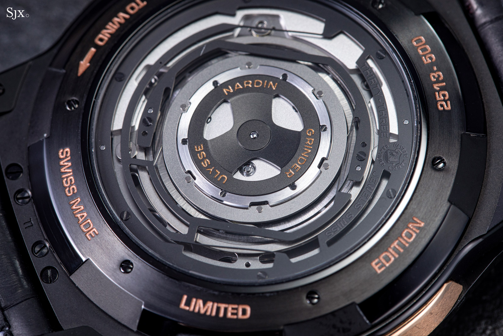
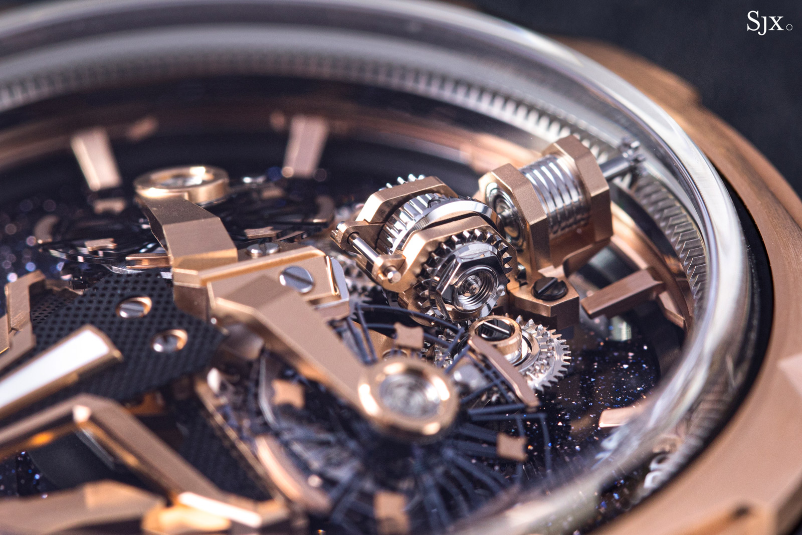
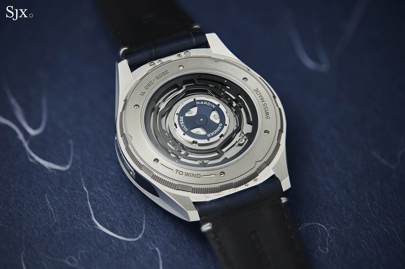
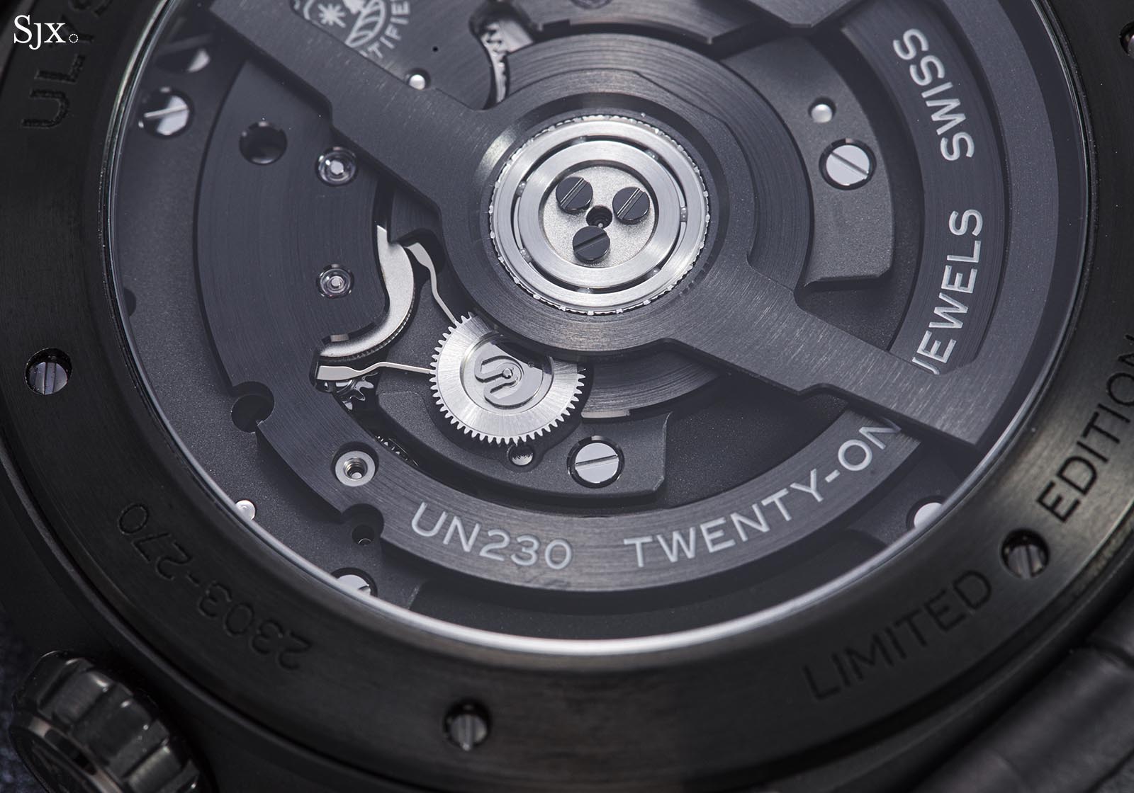
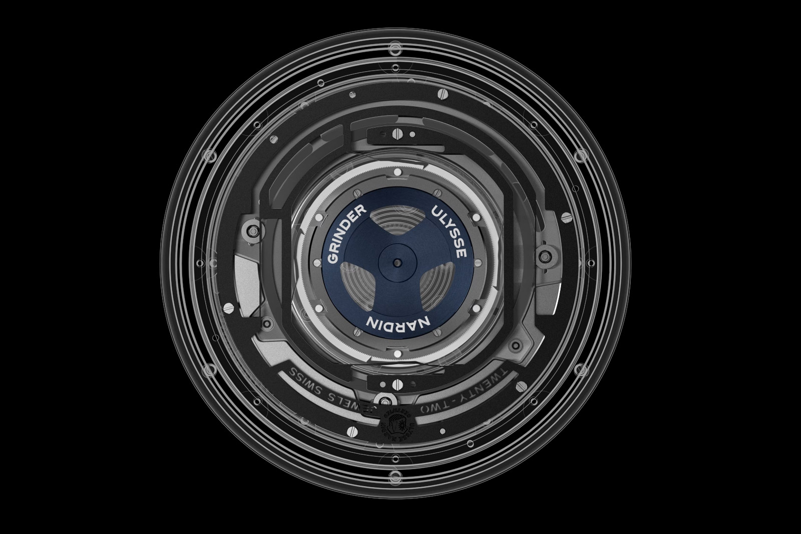
The Grinder exhibits a spread-out construction, with its different components arranged concentrically. Starting from the centre, the blue wheel is the ratchet (with fine wolf’s teeth barely visible on its rim) which is kinematically connected to the barrel arbor. Working against the ratchet are two pairs of pawls, attached to a complex and large black frame. Visible under the black frame is a silver coloured ring, making up the actual rotor. The execution somewhat resembles a peripheral rotor.
The large black frame is a compliant mechanism, relying on flexible blades to create virtual pivot points under tension. The outer frame is partly anchored to the movement’s backplate (as indicated by the screws) while the inner frame is supported by symmetrically arranged blades. The inner frame further extends four flexible pawls towards the ratchet winding wheel.
The silver ring rotor is perfectly concentrical with the ratchet wheel, while the inner frame isn’t. The inner frame (engaged with the rotor underneath) plays the part of the eccentric cam in the Magic Lever system – not having the same geometrical gyration centre, the interaction rotor – frame results in a bobbing motion transmitted from the former to the latter.
In turn, the translating motion of the inner frame makes the four pawls selectively engage the ratchet. They act in sequence and only perform a pulling action. The flexible blades always force the inner frame towards a neutral position, which is always impeded by the rotor. The inner frame is thus bound to be guided by the rotor (regardless of its direction of swing).
The large diameter of the winding ratchet gives the pawl mechanical leverage, so the final torque reaching the arbour is sufficient to wind the powerful mainspring. Ulysse Nardin claims a winding efficiency twice as large compared to its classic automatic system found in the workhorse UN-118 for example.
The workings of the Grinder system can be difficult to grasp at first, but the animation below helps in getting the gist of it. Note how the fast-moving rotor moves the frame with a slow translational motion.
Concluding thoughts
The Ulysse Nardin Freak started as an exceptional timepiece in 2001 and has since evolved into an intriguing collection. Since the original, many and diverse models were launched under the ever-growing collection. Some of them kept close to the classical Freak architecture, while others were experimental or concept watches that reimagined not only the movement construction but even ventured far into materials science. The InnoVision and DiamonSil in particular employed cutting-edge applications of novel materials.
Over its two decade lifespan, the Freak collection proposed many interesting technical solutions. This three-part series – you can find part I and part II here – was not meant to index all the related inventions, but to outline the principles of the Freak and hopefully capture its spirit of innovation. To do that, we examined the most notable features and inventions of the Freak over the years, specifically the ones that arguably sent ripples throughout the industry. Most notably, it was the profound work done with silicium components that established Ulysse Nardin as a serious innovator in horology.
Back to top.