Insight: What’s Next for the Girard-Perregaux Constant Escapement?
Perfecting the ideal escapement.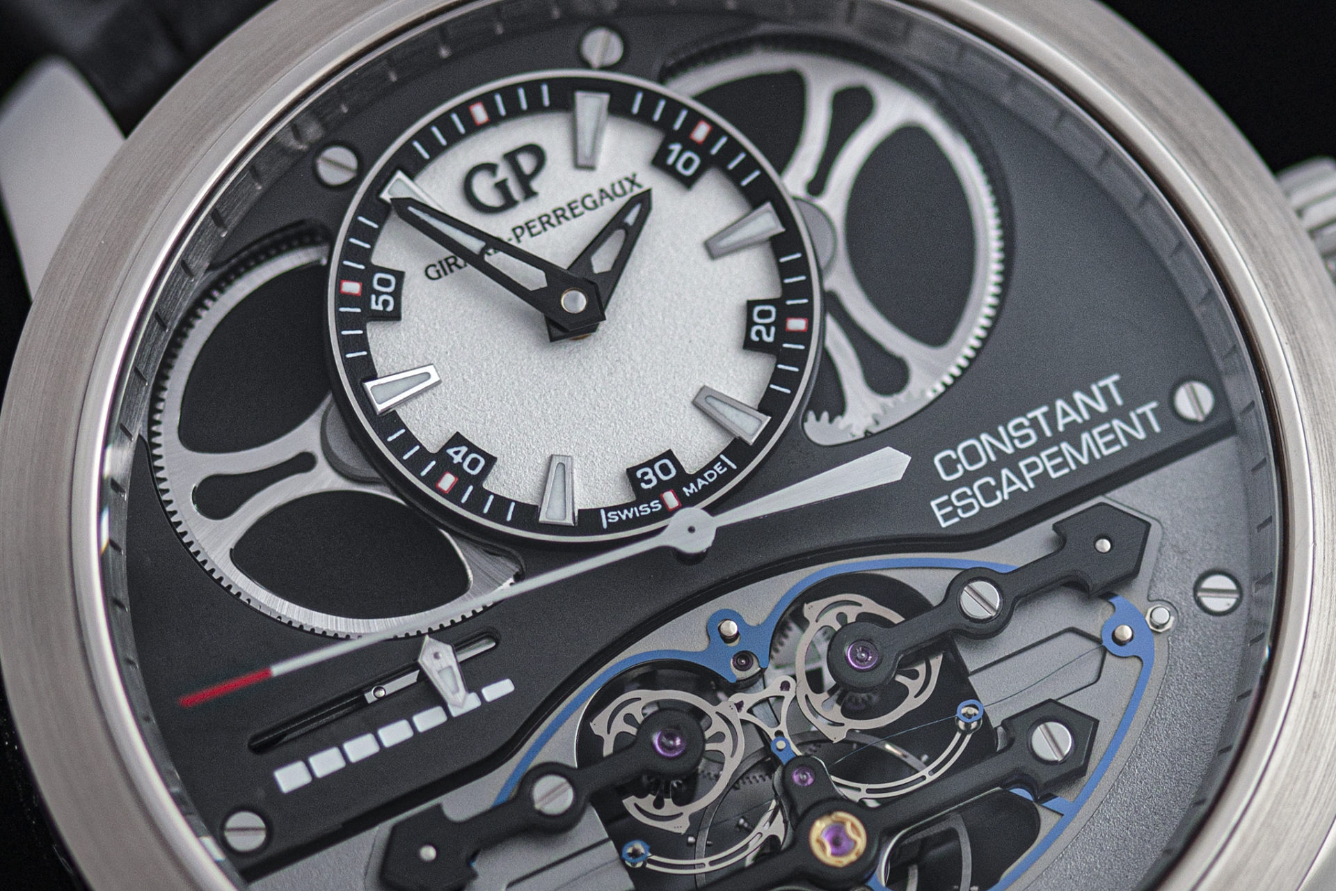
In an era of modern and accessible digital technology, the utilitarian role of mechanical timekeepers has inevitably dwindled. Yet, it is still pursued as a luxury of an artform – either of the highest finishing by hand that can’t be performed by machines, or the research and development in making a mechanical timepiece – in particular wristwatches – as accurate as possible.
One of these horological pursuits, to preserve the accuracy of mechanical wristwatches, is the supply of a constant force to the escapement. To isolate the varying torque as a mainspring gradually unwinds, some haute horlogerie watches today incorporate either a fusée-and-chain or a remontoir, which supplies a steady torque to the escapement for stable timekeeping.
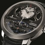
However, there is one particularly novel take on constant force released by Girard-Perregaux, in the form of a proprietary escapement. First unveiled as a prototype in SIHH 2008, the Girard-Perregaux Constant Escapement has a patented, double escape wheel system that is designed from the ground up to inherently have a built-in constant force system, thus eliminating the need of a remontoir or a fusée-and-chain.
Despite being first created 15 years ago, Girard-Perregaux (GP) is still further developing the escapement today, with a new set of patented improvements publicly available – strongly hinting at a revamped model in the near future. These patents make it worth a deep dive into the original Constant Escapement (CE) from 2008, and how the new patents improve upon the base design – illustrating how an exotic escapement can still have many possible innovations over the course of continuous development.
Bending cards
The CE is the brainchild of Nicolas Déhon back in 1997, a watchmaker who was working with Rolex at the time. Inspired by the buckling action from bending a train ticket, he had the idea that a buckling blade spring can deliver a consistent force to drive an escapement. Thus, he filed a patent the following year and developed prototypes under Rolex, but couldn’t get them to work at the time with conventional metal springs due to the tight tolerances required.
After joining GP in 2002, Mr. Déhon serendipitously revisited the CE concept a couple of years later. This is both due to Rolex withdrawing the original patent in 2004, and the introduction of silicon in watchmaking. With full support from GP, it was then finally that Mr. Déhon was able to construct a working prototype, which he then presented in SIHH 2008 and re-patented.
It is noted that while Mr. Déhon had left GP in the same year, GP picked up where he left off and further optimised the prototype into a commercial wristwatch, which was eventually unveiled in 2013. Fundamentally however, this updated movement largely works similarly to the 2008 prototype and patent.
Thus, the following writeup explores how the CE prototype works based on Mr. Déhon’s 2008 patent, EP2105806, which also applies to the commercially-released version of the CE wristwatch, and looks at the company’s most recent patents and what it might mean for them moving forward.
The Constant Escapement explained
Fundamentally, a watch’s movement stores large amounts of energy in a mainspring barrel, which then trickles down to the escapement via a set of wheels, the going train. The escapement collectively consists of the escape wheel and balance wheel, which regulates the release of energy from the mainspring barrel at a precise rate – this is the timekeeping accuracy of a movement. However, as the mainspring unwinds, eventually the torque it supplies to the escapement also decreases, which may affect the consistency of the escapement.
Constant force devices act as a buffer between the varying torque of the mainspring, to minimise, or eliminate the effects of the torque fluctuation on the escapement. One solution is to install a fusée-and-chain into the mainspring barrel system, which regulates the varying torque via changing gear ratios akin to how a bicycle chain has multiple sprockets of different sizes. Another constant force approach is by installing a remontoir, which is an intermediate, smaller spring that acts as a buffer between the mainspring and the escapement.
The CE however, inherently integrates a constant force device within the escapement itself – thus in theory, supplying consistent impulses to the balance wheel without any worry of uncertainties or variations occurring within the mainspring and going train.
In summary, while the operation of the CE appears complex, it can be easier understood by looking at it as having two distinct parts – a twisting blade spring that stores and releases consistent force to the balance wheel by unbuckling, and a double escape wheel system that recharges the tension of the blade spring.
The core idea of the CE is the buckling action of a beam structure. A simple analogy is the flexing of a playing card between your fingers, causing it to flex in an arch back and forth. More broadly speaking, such bending objects fall under an umbrella of devices known as compliant mechanisms.
The “snapping” action creates a predictably consistent force to power an escapement. This is the key element of the CE – a long and incredibly thin, suspended blade spring, spanning across the escapement. It is only possible to have achieved the required fine tolerances to make the CE work, by fabricating this blade spring out of silicon as a single part.
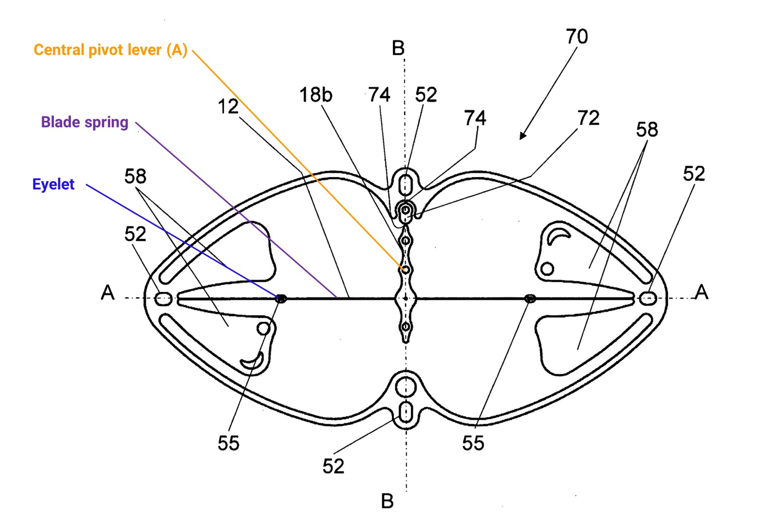
The monolithic, single-part silicon blade spring in its unbent state.
The silicon blade spring has a central pivot lever (A), which divides the blade spring in two halves and subtly twists the springs into an “S” shape in either direction when rotated. When twisted, the blade springs store energy in an “quasi-stable” state, whereby a slight push will result in the spring unbuckling in the other direction, releasing a predictable and constant amount of energy.
The pivot lever (A) acts as one half of the traditional pallet fork of the escapement, and interacts with the roller of the balance wheel. As the balance wheel swings one way, its roller pushes the pivot lever (A), which in turn slightly undoes the twist of the blade spring.
The most crucial part occurs here – this motion is just enough to cause the blade spring to “unbuckle” and flip into the other “S” direction, forcing the pivot lever (A) in the other direction, and at the same time delivering power to the escape wheel via its roller, like a traditional escapement, but with a consistent impulse of energy.
With the blade spring unbuckled it is now in a stable, relaxed state and does not store energy – thus needing to be recharged before the next swing of the balance wheel. This is where the remainder of the mechanism comes in: the unlocking of the escape wheels to supply power back to the blade spring.
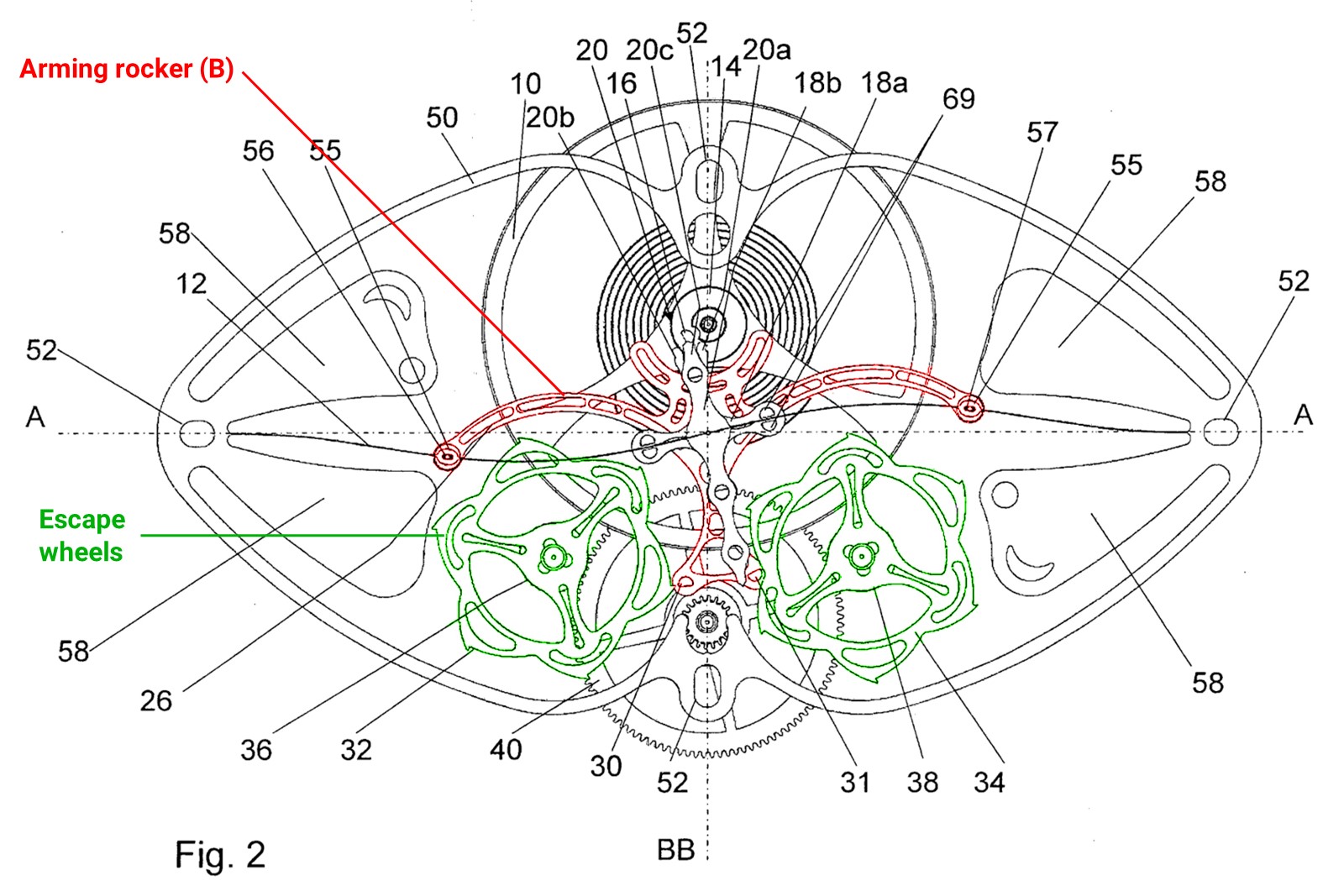
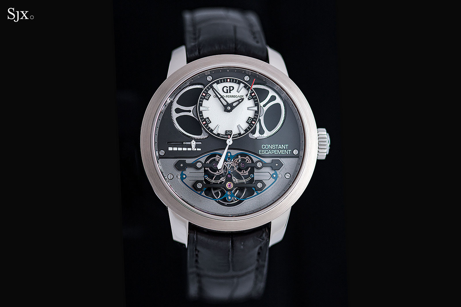
The arming rocker mechanism, which recharges the blade spring’s energy between ticks and tocks
In the middle of the left and right blade springs are hollow eyelets, which loosely interacts with an arming rocker (B) via pins within the eyelets. This arming rocker (B) locks and unlocks a pair of escape wheels which are geared together and driven by the going train – the pair of escape wheels makes the CE a double wheel escapement, reminiscent of the natural escapement originally conceived by Abraham-Louis Breguet in 1789.
During unbuckling, the hollow eyelets along the blade spring pushes the arming rocker (B) via its pins, rotating it slightly out of the way to unlock one escape wheel. The unlocked escape wheel then freely spins as powered by the going train, providing a relatively large force by pushing the arming rocker (B). This toggles the arming rocker (B) towards the other direction until it blocks the other escape wheel. During the toggling action of the arming rocker (B), it transmits force back to the blade spring via the eyelets, re-twisting the blade spring and thus recharging its stored energy, ready for the next cycle.
To summarise, the CE is a carefully coordinated constant force system using a blade spring – acting as a remontoir as close to the balance wheel as possible – with a recharging system consisting of double escape wheels. One can’t be faulted to assume that such a novel integrated escapement may therefore lack room for future upgrades, due to the seemingly restrictive nature of how the systems have to interact with each other.
New patents
Thus, it is fascinating that even a delicately integrated escapement still has room for major mechanical variants and potential improvements in its core design. At this stage, it is a team collaborative effort – new patents were filed by Nicholas after he returned to GP, and also by other GP watchmakers involved with the project.
While these patents strongly hint at an upcoming updated model of the CE, it is to be made clear that these patents may not necessarily be in a final product. But rather, it showcases the potential improvements that can be made to the existing escapement.
Three such patents are publicly available, and are presented as follows. It is noted that each patent presents a separate variation to the original design, and thus are mutually exclusive in terms of implementation:
EP3599514 (2018)
This patent serves to improve the overall efficiency and reliability of the escapement. Two variants are presented: one with the previous double escape wheel setup, and the other intriguingly with a single escape wheel configuration.
In summary, the overall escape wheel portion of the design has been altered with smaller wheels, and the arming rocker has been tweaked. However, this leads to a crucial addition to the revised design – since both escape wheels rotate in the same direction, it makes operation of the escapement asymmetrical, as the arming rocker engages one escape wheel at different positions.
Thus, a third blade spring, a compensation spring, can be seen integrated into the upper right of the escapement depicted in the below diagram. This balances the forces of both escape wheels to be symmetrical, allowing the arming rocker to swing symmetrically and thus making the overall escapement more reliable.
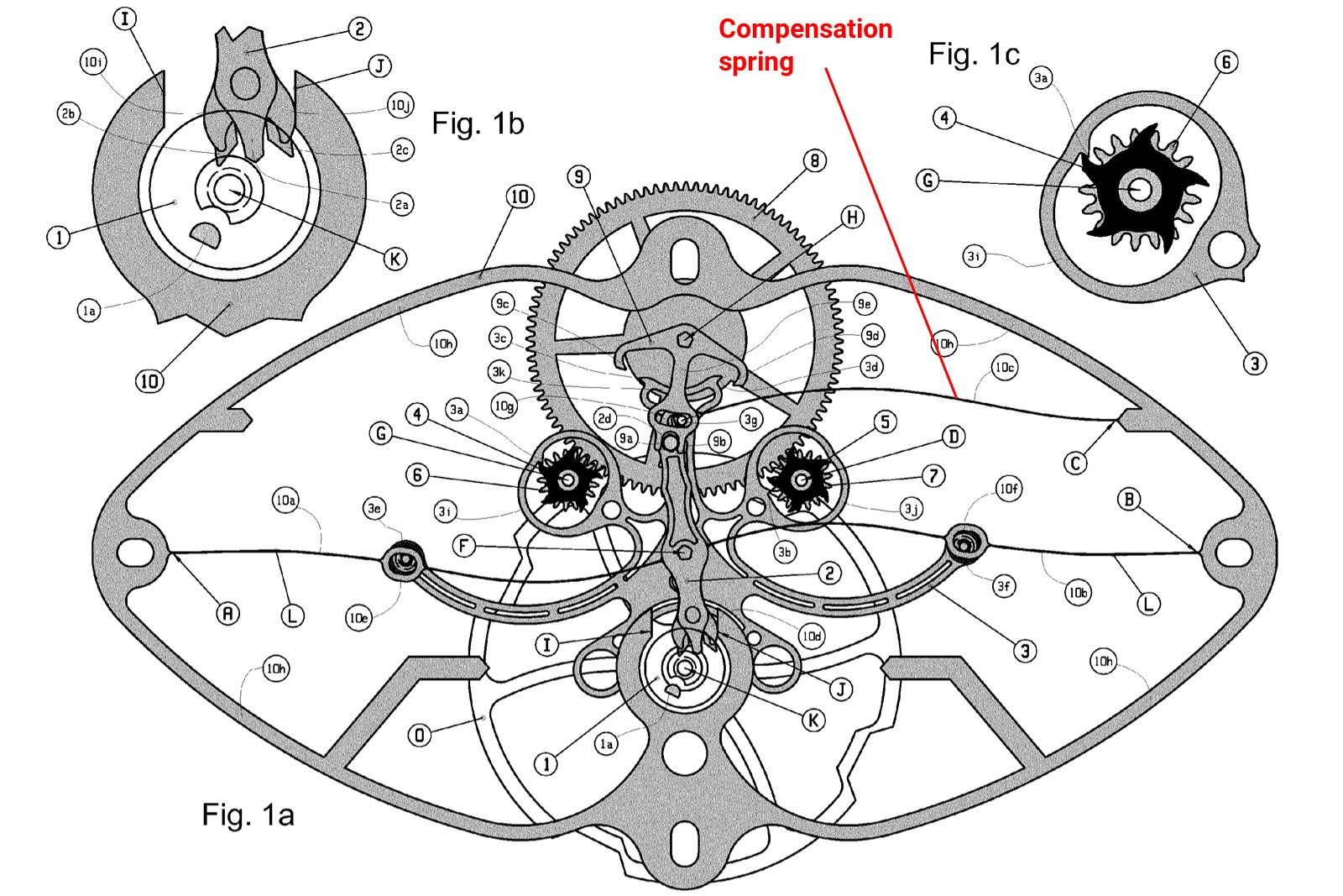
The double wheel escapement with a compensation spring to address the asymmetrical nature of the escape wheels
This patent also presents an alternative design, which has a single escape wheel using a similar modified arming rocker. Again, as the arming rocker engages the escape wheel at different locations between ticks and tocks, the compensation spring is still needed to balance the forces between the left and right swing of the arming rocker.
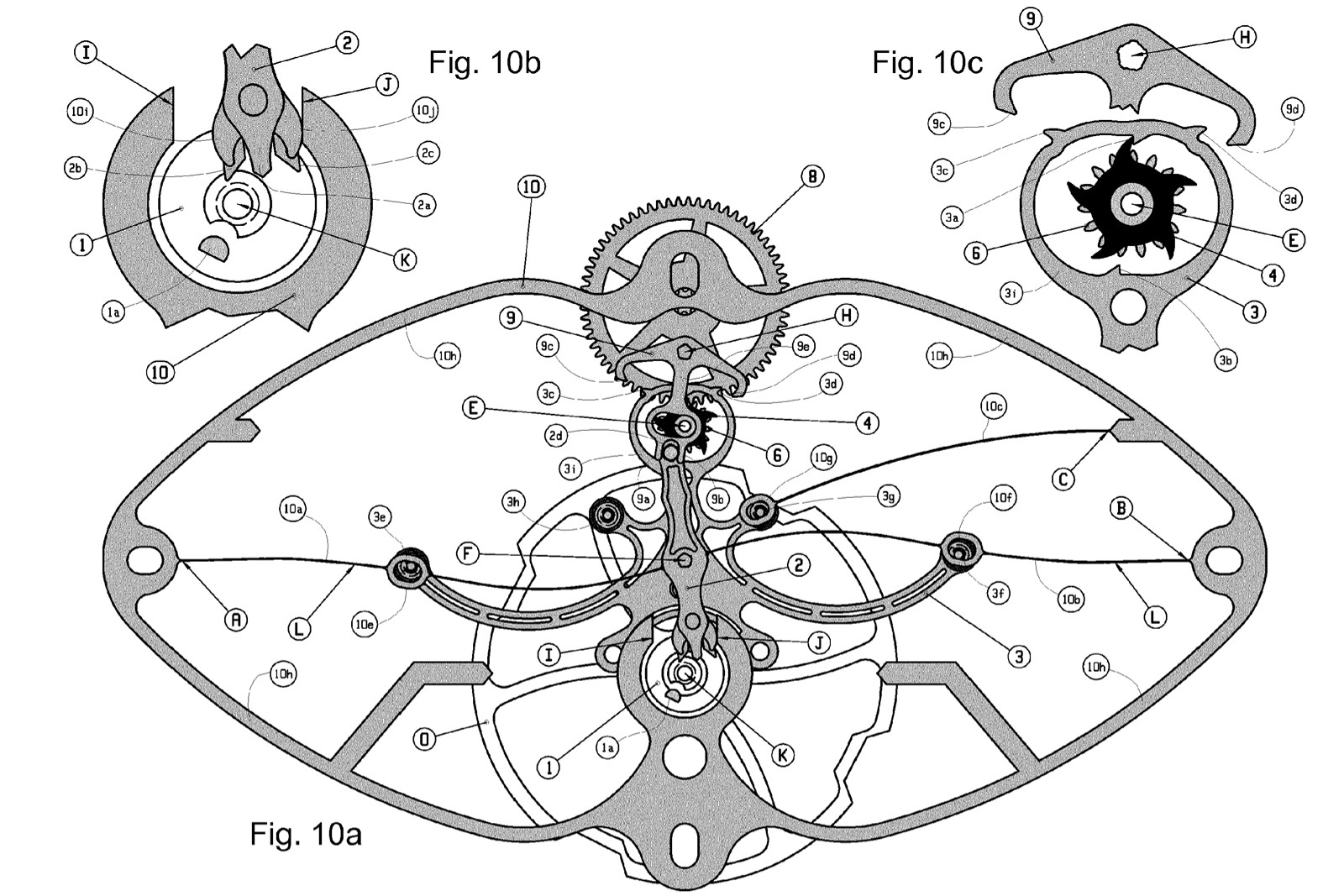
The single wheel escapement variant, also with a compensation spring
EP3623875 (2018)
Due to the nature of the CE having an arming rocker that toggles back and forth, there is the possibility of rebound as it collides against the escape wheels during the locking phase.
Thus, patent EP3623875 proposes the solution in the form of a wedging mechanism. The escape wheels are entirely redesigned in shape – almost like cams – such that it “wedges” against the arming rocker gradually to lock. The gradual wedging prevents any chance of the arming rocker to dislodge or rebound, thus improving overall efficiency of the design.
It is noted however, that due to the escape wheels having a long sliding surface for the wedging operation, proper lubrication is essential for reliable operation of this design.
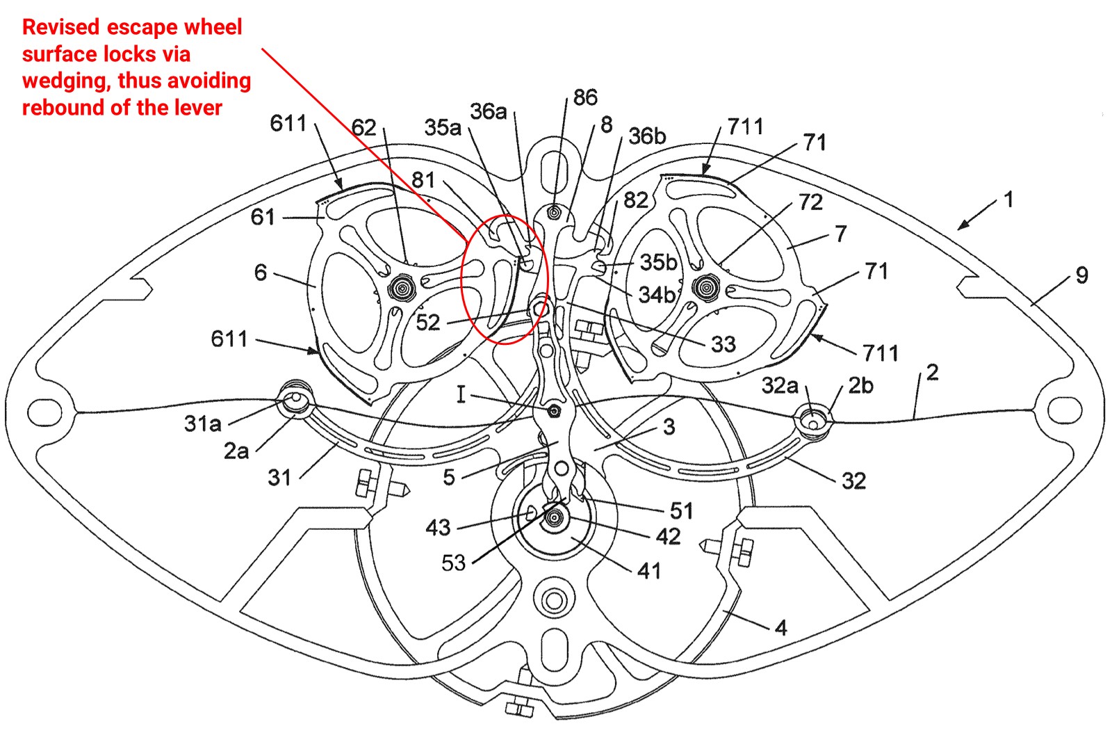
The redesigned escape wheels to cater for a wedging mechanism against the rocker arm
EP3273308 (2016)
This patent is perhaps one of the most intriguing variations to the original CE design. It alters the locking/unlocking mechanism of the double escape wheel with a single escape wheel instead. But most importantly, it redesigns the arming rocker as a cam-controlled system instead.
More precisely, a Reuleaux triangle cam is installed under the single escape wheel. This serves as a cam, which controls the perturbation motion of the arming rocker via a fork, instead of relying on escape wheels and pallets.
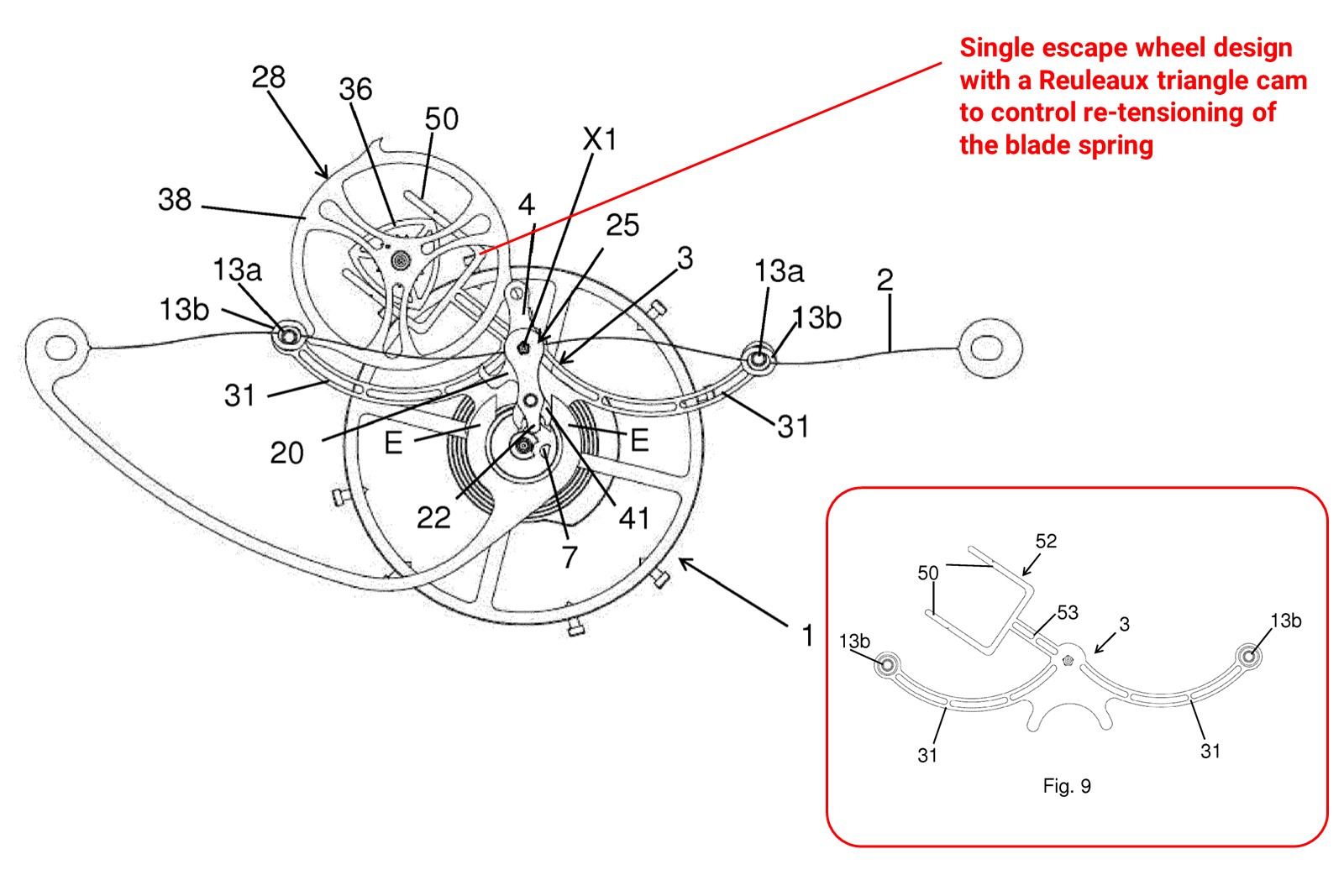
The arming rocker is now equipped with a fork that’s controlled by a Reuleaux triangle cam
The advantage of using a Reuleaux triangle cam is that it tightly engages with the arming rocker, thus allowing for smooth rocking back and forth without any chance of the arming rocker disengaging or rebounding against the escape wheel. However, being paired with the escape wheel means that the Reuleaux triangle cam rotates relatively quickly, and thus again, adequate lubrication is required to allow smooth engagement with the arming rocker’s fork.
Future plans?
The three patents above describe significant upgrades to the existing Girard-Perregaux Constant Escapement design. From a solely academic perspective, it is intriguing that even an exotic escapement can still have plenty of room for tweaks and variations.
And this doesn’t count the fact that more developments are likely under way within the R&D department at Girard-Perregaux, still tightly under wraps. With such developments made over recent years despite the original timepiece debuting as far back as 2013, it is not surprising that hopefully, a revised version of the Constant Escapement may be released in the near future.
This was brought to you in partnership with Girard-Perregaux.
Back to top.