In-Depth: The Microscopic Magic of H4, Harrison’s First Sea Watch
A heart of diamond.
One can understand the opacity of the first published analysis of John Harrison’s first sea watch, colloquially known as H4 and the forerunner of the marine chronometer, in The Principles of Mr Harrison’s Time-keeper. Edited by the British Astronomer Royal Nevil Maskelyne, it was published by the British government in 1767; and hereafter referred to as Principles.
Principles was both incomplete of enough information to allow the duplication of the watch, which Harrison (1693-1776) started in 1755 and finished in 1759, and contained somewhat incoherent description that only makes sense a posteriori after examination of the watch.
‘Principles of Mr. Harrison’s Time-keeper’
Amazingly, it was one hundred years later the next review took place. I can echo Harrison M. Frodsham’s comments in his review in Horological Journal of May 1878 when he said, “Former explanations taken from Harrison’s description are necessarily unsatisfactory, as his was very obscure, probably purposely so.” Although this may be dismissed as 19th Century gossip by some scholars, this may have arisen in part to protect any military advantage, given the importance of H4 to maritime navigation.
Considering H4’s historical performance, it is odd that the otherwise comprehensive A Treatise on Modern Horology in Theory and Practice (2ndedition) by Claudius Saunier, published in 1887, barely mentions Harrison and certainly not H4’s technical content. Perhaps it was because it was so quickly built upon by the work of John Arnold (1736-1799) and the new approaches of Pierre Le Roy (1717-1785).
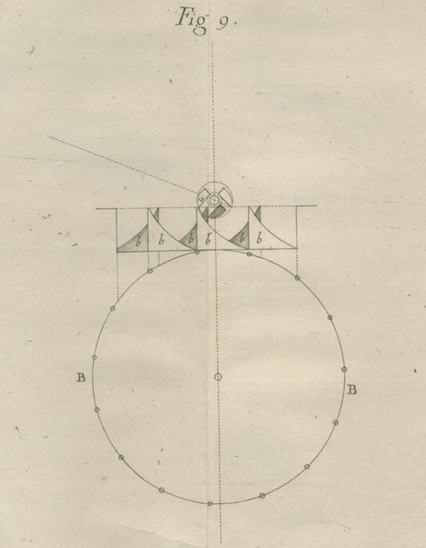
A diagram from Principles gives a tantalising clue as to the escapement mechanism in H4
But another diagram from the same may leave the reader baffled as to how it purports to show the same part
It is less easy to understand how it still remains hard to get detailed information on H4 – 305 years since the Longitude Act. The Royal Navy (the owners) had always been reticent to allow close examination of H4, to stop poor copies being made and certain documents remain difficult for the general public to access. Getting to the bottom of the fundamental principles of the watch has remained a challenging process. Fortunately this is sure to improve as more archives become digital.
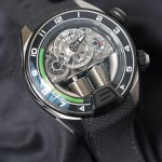
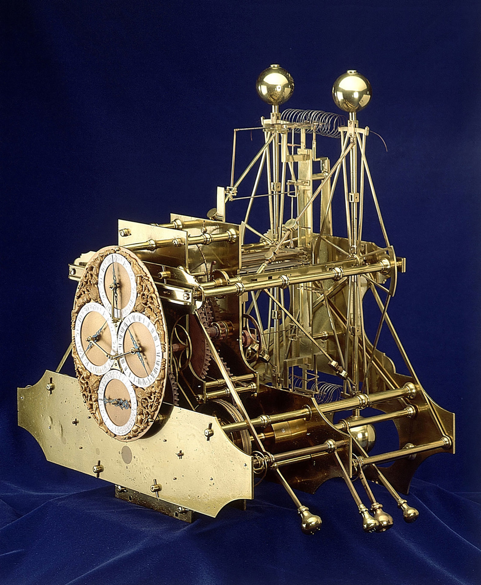
This story is not an exhaustive breakdown of H4. For that, the reader should familiarise themselves with the chapter on Harrison in The Marine Chronometer – Its History and Development, written by British naval officer and horological scholar Rupert Gould, or later material from the National Maritime Museum and view the overall mechanism of the replica (its movement is pictured at the top of the page) – the swansong of Derek Pratt, who started it in 2004 but passed away in 2009, and fittingly completed by Charles Frodsham in 2014.
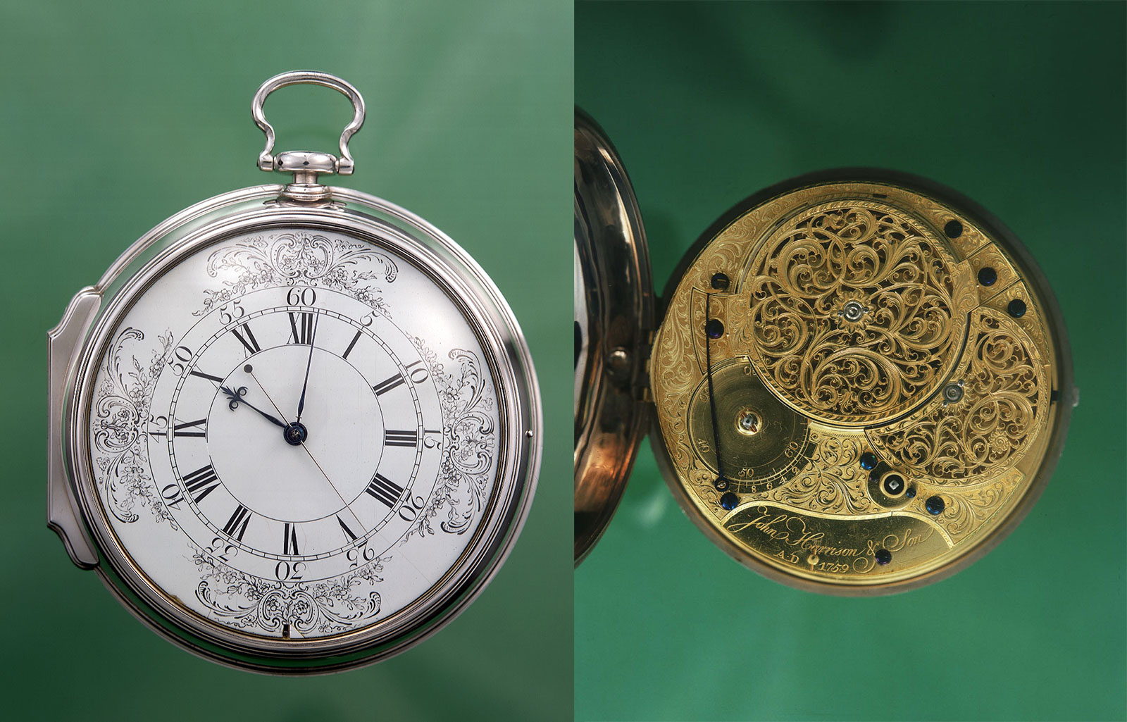
H4 and its movement. Photo – National Maritime Museum
By piecing together information from the replica, the observations of Gould during his restoration of H4 from 1920 to 1933, Hird et al’s paper with optical microscopy of Harrison’s escapement pallets, and pulling out a 278-year old treatise by Antoine Thiout the elder on horology, we can now understand a little better what is going on at the most fascinating point in the whole of H4’s mechanism: the escapement. A quick overview of the watch would not hurt, nevertheless.
The H4 sea watch
Overlapping with the failure of his large clock approach, the “sea clocks” H1, H2 and H3, Harrison had success with the design of a watch that incorporated some of his ideas; the “Jefferys” watch made for Harrison’s personal use by fellow watchmaker John Jefferys (1701-1754). Encouraged by its performance, Harrison realised the large clock concept was dead and he set about his first sea watch that was to be a mere five inches or so in diameter.
The Harrison H1 sea clock. Photo – National Maritime Museum
Christened H4 by Gould, the watch was essentially an extra-large pocket watch wound daily by key, with its 30-hour power reserve being stored in a steel spring inside a brass barrel. This in turn pulled a chain barrel and fusee containing Harrison’s “maintaining power” system. This system alone could keep the watch running for eleven minutes using a separate spring while the mainspring was being wound.
Also incorporated into the movement was a device tracking the position of the fusee, in order to stop the watch, by means of a frictional brake on the balance, half an hour before the mainspring fully ran out of power so as to allow the remontoire to keep functioning. This was critical because if the watch was allowed to stop, one could not just agitate the balance to restart its motion, instead the remontoire detent had to be unlocked, something only a watchmaker could do and tricky while at sea.
At the base of the fusee was a great wheel driving the centre wheel and the going train was jewelled from the third wheel onwards. The remontoire operated eight times per minute and drove what looks on first glance like a verge escape wheel but intriguingly without the usual undercut teeth. The balance was sprung by a tapered spring with three turns managed by a temperature compensating mechanism to slightly alter the effective balance spring length. The regulating device was ultimately not deployed with the rack and pinion mechanism being removed.
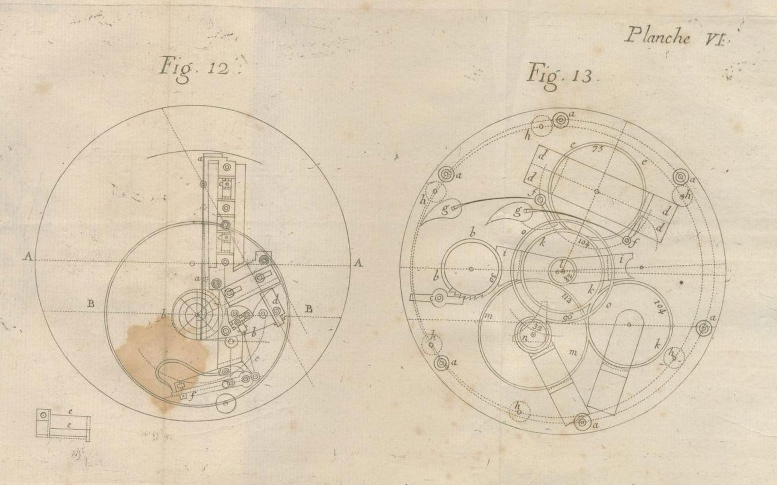
From ‘Principles’, drawing 12 shows the balance (BB), temperature compensator (aa) and balance spring (bb). Drawing 13, spring barrel ratchet (bb) and click (c), the cannon pinion (l), minute wheel (mm), hour wheel (oo).
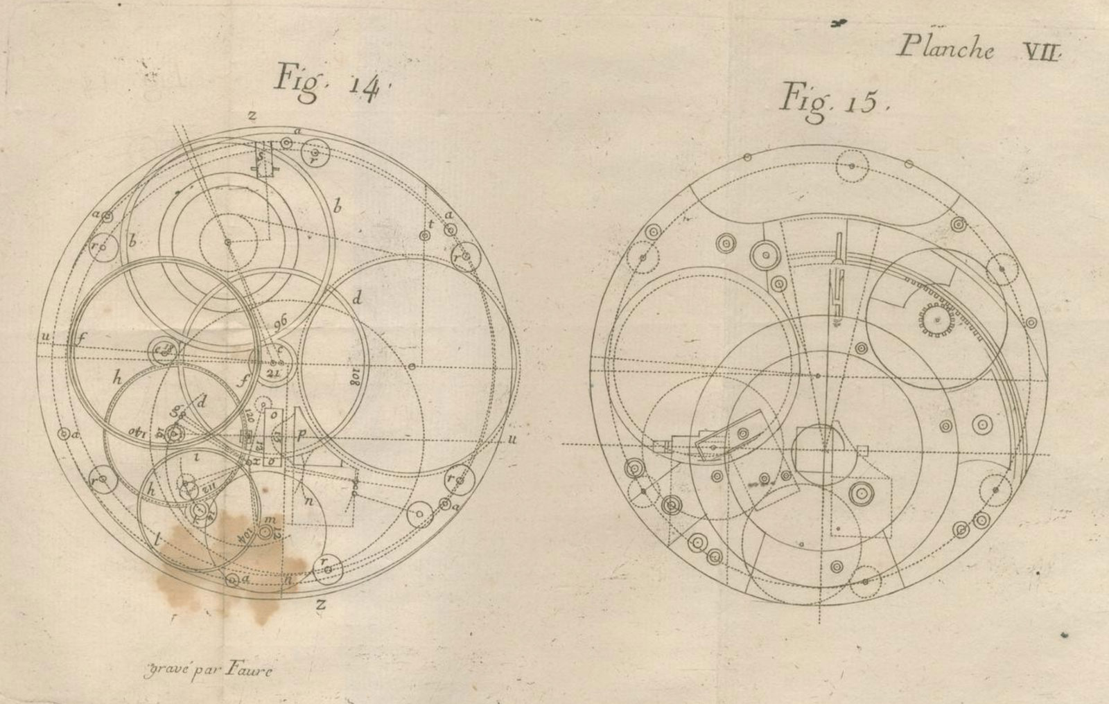
From ‘Principles,’ drawing 14 appears to show the going train layout but does not divulge the complex nature of the drive to escape wheel (oo), nor the way the remontoire is integrated.
Harrison’s pallets
The pallets of the escapement were “D” shaped, approximately 2mm by 1mm by 0.4mm and made of diamond. A cycloid pin that touches the hairspring to improve its isochronous performance was also not added till after its maiden voyage on board the HMS Deptford to Jamaica in 1761. It was running at 2.5Hz and with a large amplitude described by Harrison as “more than two thirds the circle”, or +/-120 degrees.
Wondering how on earth anyone could have taken a verge– the primitive escapement invented in the 14thcentury – to chronometer levels of performance, I was really intrigued. Now, on a standard verge the pallets are arranged essentially perpendicular, 90 to 100 degrees or so, to each other. There is a large recoil, a limited balance amplitude and it is sensitive to variations in driving torque even with the later versions having some form of balance spring.
Taking a look at Thiout the elder’s work we find the following:
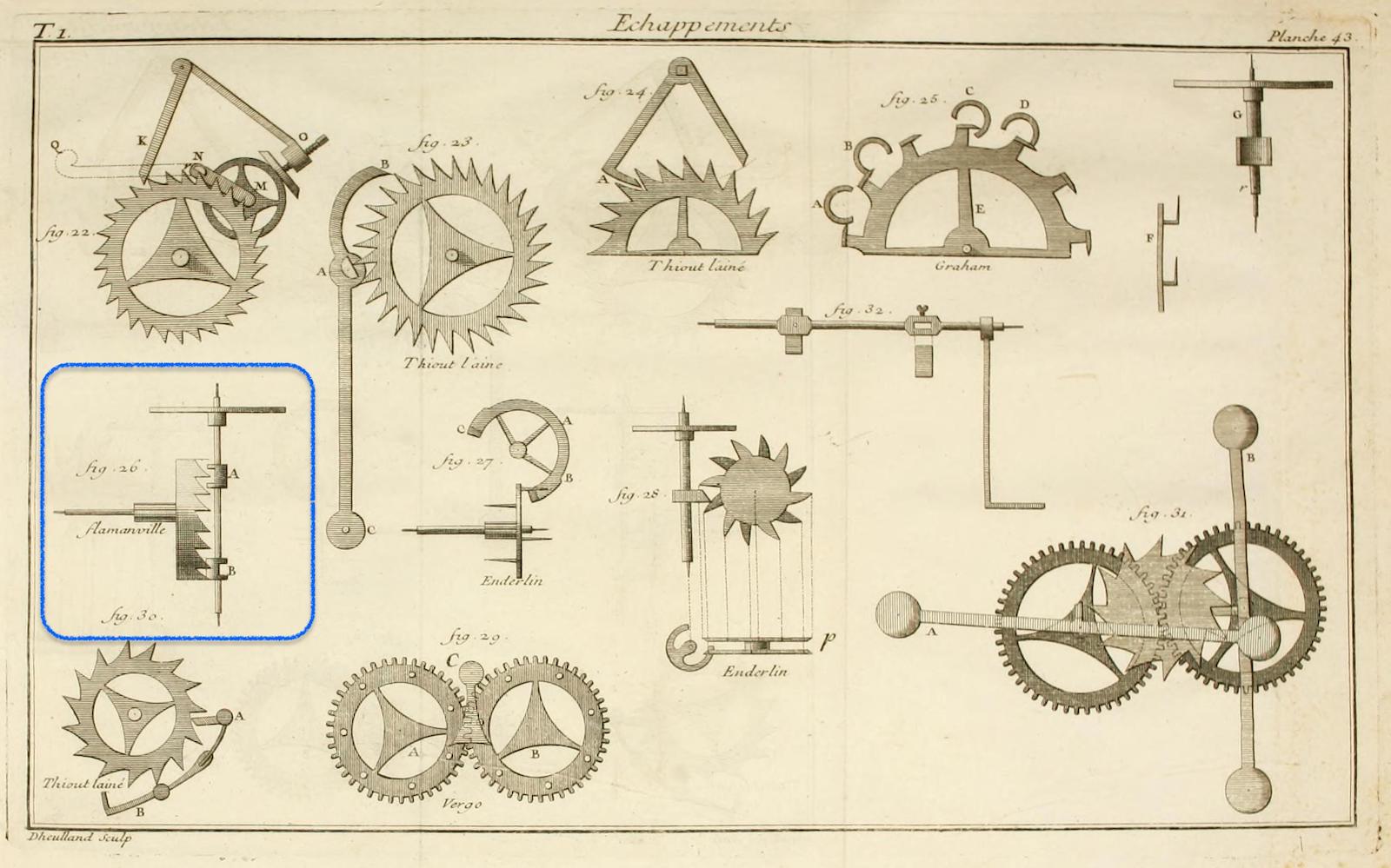
Thiout the elder wrote, referencing the escapement circled in blue above, “Fig. 26. is a two rest escapement from Mr Flamenville (sic), which has been the focus of many English Watchmakers, where it has been applied for three or four years……., it has been applied to watches that one has estimated to have varied only a few seconds in a month. Its defect is to be too susceptible to variation when the oil becomes thick.”
Based on the year, it must be likely that Harrison took this mechanism as a basis for his watch because of its stated potential timekeeping, and probably considered he might mitigate the oil issue by further improvements, which he eventually achieved.
On Harrison’s version, the flats of the two pallets at the bottom and top of the balance pivot are parallel to and facing each other. The cylindrical outside of them face apart providing frictional rest. This arrangement also allows a large balance period and critically, Harrison’s pallet backs are cycloidally shaped; the Flamenville escapement pallets had circular backs. This attribute was not by accident and a clear improvement.
Gould writes in The Marine Chronometer: “The pallets are very small….. Moreover, instead of being steel, they are of diamond, and their backs are shaped to cycloidal curves. …… the points of the teeth rest, for a considerable portion of the supplementary arc …….upon the backs of the pallets, and tend to assist the balance towards the extreme of its swing and to retard its return.”
Furthermore, Frodsham says in his 1878 Horological Journal article H4’s escapement had “a good deal of ‘set’ and not so much recoil, and as a result the impulse came very near to a double chronometer action.”
Maskelyne gives clues to Harrison’s insight in Principles, “A certain size is best for the pallets, or rather a certain proportion between the diameter of the circle described by the edge of the pallets and the diameter of the balance wheel. This was first suggested to Mr Harrison from bell ringing; for he could bring the bell better into a motion, by touching it from time to time somewhere near the centre than the near circumference; because in the first case his hand moved quick enough to follow the bell.”
Schematic layout of the balance and pallets from Frodsham, ‘Horological Journal’ 1878
So let us walk through the action.
The escape wheel teeth interact with the diamond pallets as follows: starting from the drop (where the escape wheel is free to advance) the balance is swinging and the flat face of a pallet arrests a tooth of the escape wheel. The balance keeps swinging due to its momentum and the pallet forces the slight reversal of the escape wheel.
The rotating pallet rides over the escape tooth face and onto its curved back side. The curved back in conjunction with its offset from the balance pivot axis means that the overall curve is one of a decreasing radius. This means the escape wheel slightly advances continually during this frictional rest period. The curved back side of the pallet is acting like a cam.
The key thing is that the higher the amplitude of the balance wheel, the more the escape wheel advances and can impart a little more energy to the balance wheel. As the balance swings back its return is ever so slightly delayed by the reversal of the escape wheel. This behaviour helps larger amplitude swings take ever so slightly longer and is a key part of H4’s chronometric performance.
As the balance returns to its centre, the pallet then rides over the escape tooth face onto its impulse flat and the tooth gives new impulse to the balance until the edge of the pallet is reached and then the opposite tooth is dropped onto the opposite pallet face and the process begins again.
Jonathan Betts, Curator Emeritus at the Royal Observatory (National Maritime Museum) adds, “The critical feature in this escapement is that the impulse is delivered to the balance at a very short radius from the centre of the balance, giving the balance great ‘dominion’ over the escapement. In a sense it is a form of detachment as it detaches the balance from the mechanical effects of the escapement action. This is why Harrison stated “..the less the wheels have to do with the balance the better”. Harrison WAS an exponent of detachment! But is was a ‘dynamic’ detachment, not a literal one.”
Material science
Harrison pursued diamond pallets to deal with the impulse. In his 1763 manuscript, he refers to other common pallet materials of the time “not being able to last a month”. I don’t know, but I can imagine he must have tried the pallet geometry out first on these easier-to-work materials.
And so to the geometry of the diamonds. From Hird et al, the following microscope pictures taken showed the upper pallet:
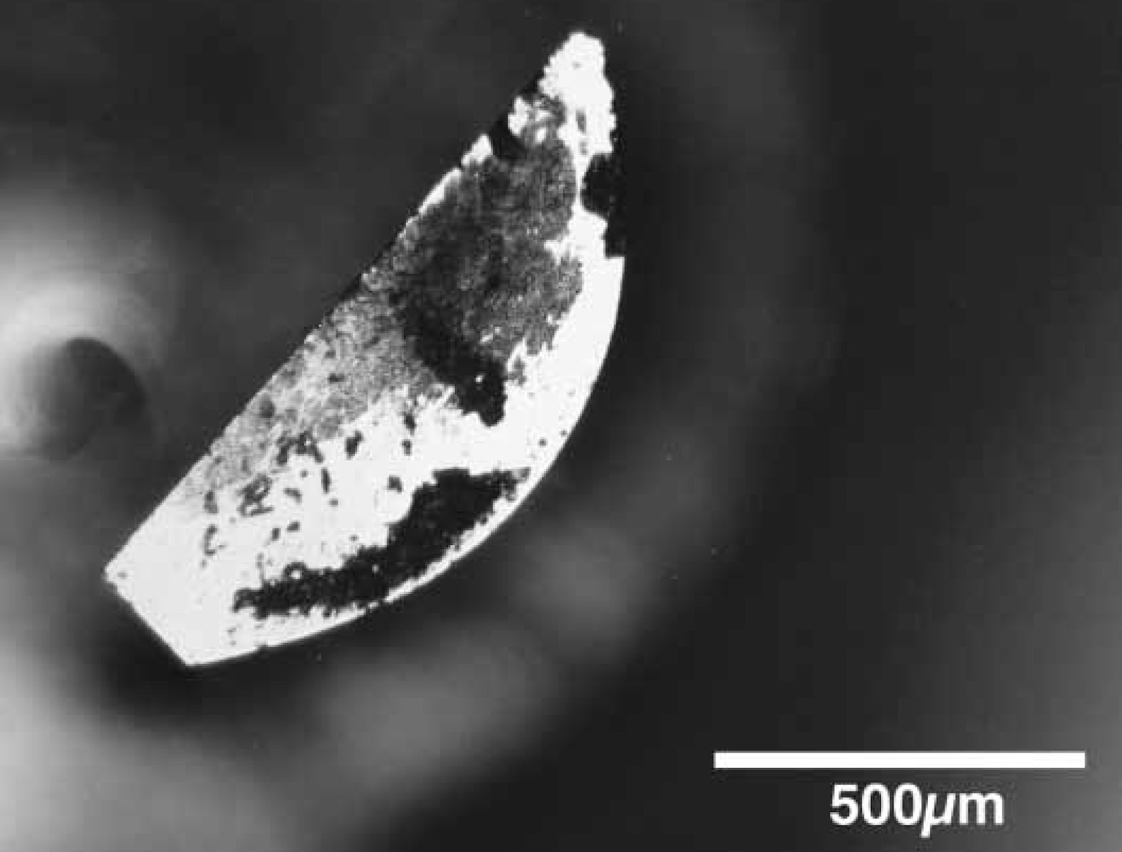
The upper pallet. Photo Taylor & Francis Ltd 2008
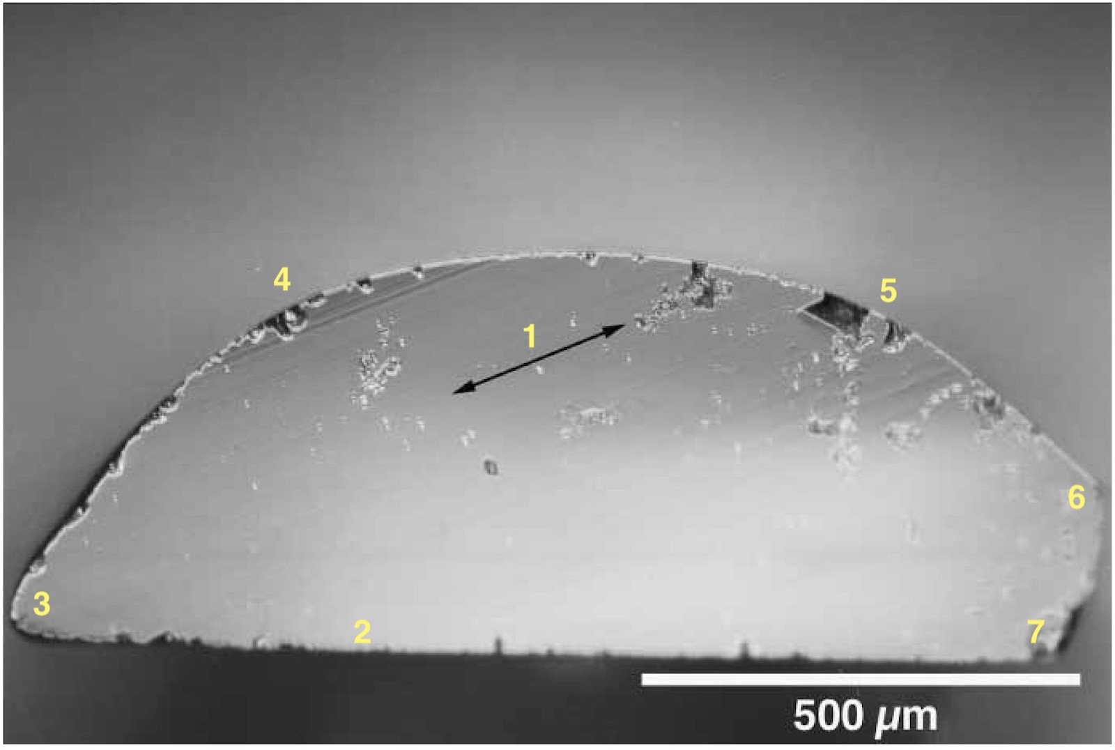
The lower pallet with annotations by the author. Photo – Taylor & Francis Ltd 2008
It can be seen that the actual pallets deviated from the shape described in Principles. The upper and lower pallets subtly differed in the particular curvature of the pallet backs; the upper pallet more smoothly curved, while the curvature on the lower pallet might have been achieved by forming a number of flattish faces, perhaps up to four, and the edges of these subsequently blended together to form the shape.
To the lower pallet I have added some annotations:
[1]: Indicates direction of lines of polish on the end; not visible in the upper pallet. Interesting, but the pallet ends have no timekeeping function.
[2, 3, and 7]: This is the impulse face, or “flat”; [3] is the end that will roll over the escape wheel tooth. Interestingly, the impulse flat is not quite flat. The plane from [2] to [7] is flat on a ruled line, but from [2] onwards it kicks up to the edge at [3]. It is hard to tell the precise radius or geometry though, it also differs from the upper pallet which appears flat.
[3]: It would be interesting to determine the radius of curvature here. There will be a high loading at this edge both just after drop and at the start of impulse.
[3, 4, 5, and 6]: The curve on the back is quite complex. The radius at [4] looks the smallest of this, flattening to [5] and then tightening. The upper pallet appears a smooth curve.
[6 and 7]: The lower pallet rear bevel is at an angle, but not 90 degrees as drawn by Harrison. With a balance amplitude of about 124 degrees maximum – Harrison refers to a total swing of 248 degrees in his manuscript of April 1763 – I am not sure the geometry at [6] and [7] matters very much. The upper pallet is close to the drawn shape.
It is the curve on this back [3, 4, 5 and 6] related to the balance axis that allows the escape wheel to keep adding impulse to the balance towards the end of its swing. This would have the effect of making his oscillator’s natural frequency less related to amplitude, in other words, more isochronous. However, the fact that the pallets are different in geometry may seem important but the reduction in radius they create relative to the balance axis dwarves the slight differences in their manufacture. We can also see the lower pallet had a slightly curved impulse face. I can certainly see why it might be advantageous to approximate more to rolling contact with the escape wheel tooth during impulse but it is barely present and probably not deliberate.
Betts believes, “The backs of the pallets are deliberately of a different radius, equating to the different effects of the ‘winding up’ and ‘unwinding’ of the balance spring – with a short spring of just 3 turns, the Caspari effect of the two is markedly different, the unwinding requiring greater correction, hence the smaller radius pallet back.”
One can only imagine the difficulty faced forming a precise target geometry hundreds of years ago on a component so miniscule using the world’s hardest material but with directional properties and natural flaws – and then having to make a pair!
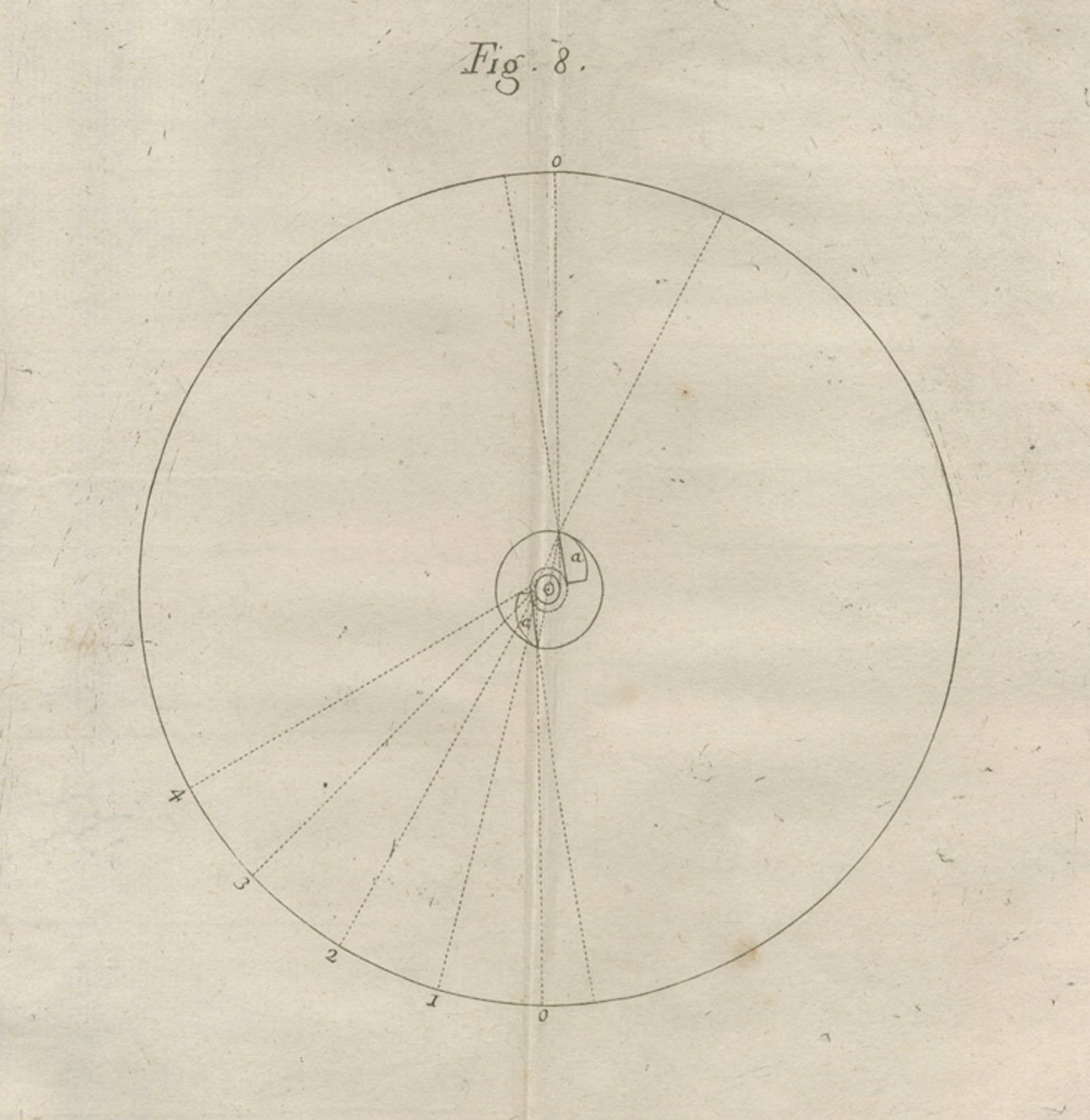
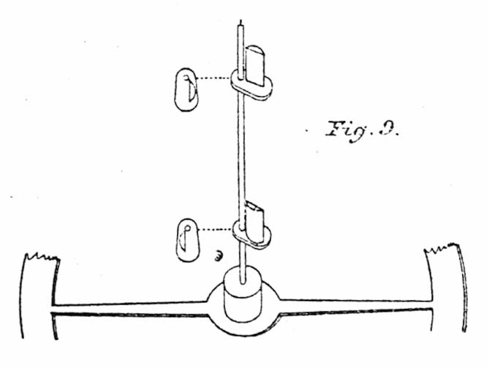
So let us examine how close H4 actually matches the described escapement geometry in Principles. According to the description in Principles, “In figure 8 [pictured at the start of the article], the centre of the curvature of the pallets is in the circumference of the punctuated circle, the radius of which is two-fifths of the radius of the circle described by the extremity of the pallets.”
I took the full image of the above lower pallet and drew some radii over it.
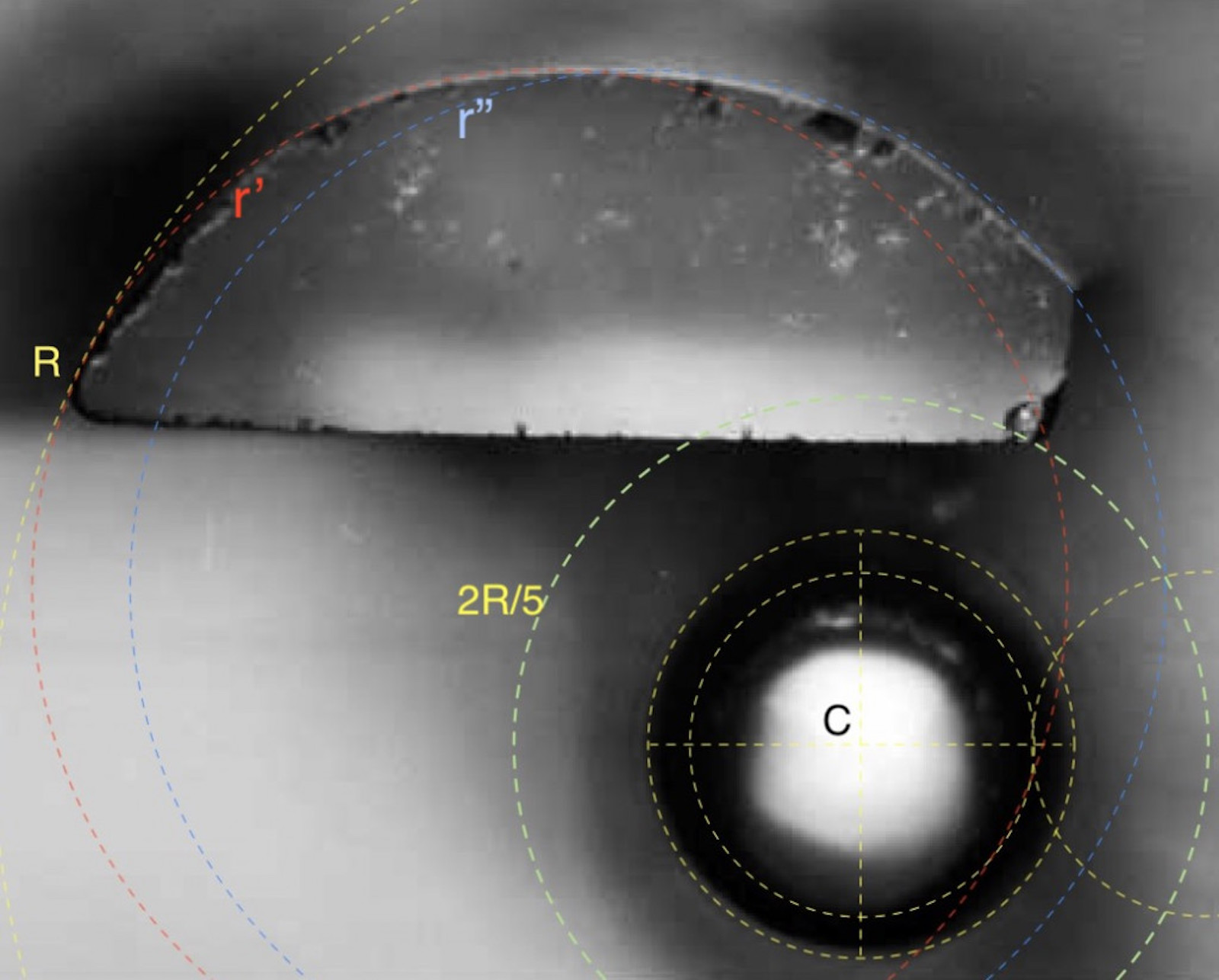
Annotations by the author. Photo – Taylor & Francis Ltd 2008
R-C = pallet tip radius
2R/5 – C = the punctuated circle.
r’-C and r”-C = the described pallet curve radius, which must be 3R/5
In summary, it is only approximately true, but it was clearly good enough. As we know, its chronometric performance was outstanding – H4 lost five seconds over the 81 day voyage to the West Indies and back.
And finally, as a fun fact, I wanted to know how much power Harrison had achieved in his oscillator. The balance, including spokes, is quoted at 28 5/8 troy grains, with a diameter of 2.2 inches, oscillating at 2.5 Hz with an amplitude of 124 degrees. We also know that the steel rim was ¼ inch wide and 0.048 inches thick.
Taking the inertia of the rim alone that gives us a rim mass of 1.205 g and an inertia of 7388 mg.cm2. This gives the H4 balance as running at approximately 7 milliwatts. That is equivalent to nearly twenty Rolex cal. 3135s (the de facto movement inside Rolex men’s watches from the 1990s until recently) beating away fully wound, but in a package just over five inches in diameter!
Tim Lake is a Fellow of the Institution of Mechanical Engineers. His lifelong enthusiasm for horology was borne from sitting on his grandfather’s knee watching the hypnotic oscillating balance of his pocket watch. Taking clocks apart furnished him with a love of all things mechanical. A recovering accuracy freak, retired 2000s blogger and contributor around the web, he graduated to putting watches back together. He now endeavours to write on topics less well covered.
Amendments September 7, 2019: Harrison referred to peak to peak amplitude rather than the modern definition of angle of swing from the escapement dead point. So clarity was added in the text and the balance power calculation was revised.
Amendments September 13, 2019: Richard Stenning from Charles Frodsham was kind enough to provide several detail points and corrections, primarily on the description on the H4’s chain and fusee, as well as its balance wheel.
Amendments January 28, 2021: Jonathan Betts, Curator Emeritus at the National Maritime Museum provided some further detail and his comments above.
Back to top.